Question about cutting Pixel Strip

nmiller0113

New elf
Joined
Oct 29, 2012
Messages
33
Location
California
I thought I understood how you could cut pixel strips but today I was reminded that I didn't completely understand it :) I have the following strips:


http://www.aliexpress.com/store/product/BLACK-PCB-5m-led-digital-strip-DC5V-input-WS2801IC-256-scale-32pcs-IC-and-32pcs-5050/701799_651897346.html


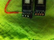
I cut them into 1/3 in the process of making a display. I ran into an issue where there were certain pixel sections would light up, but nothing beyond that in the strip would. I found that the particular pixel sections that caused this had some circuitry between the IC and the solder points. It was strange to me because that particular pixel would light up but nothing beyond it would. I'm hoping someone here can shed some light as to what I'm running into so that I at least know why and can avoid or adjust to it in the future. I was always under the impression that you could cut the pixel strips where ever at the solder points and it would never be an issue, but maybe that isn't the case. I've attached a pic for you to see the difference...you can clearly see the additional circuitry. Thanks everyone!
 

Attachments

  • IMG_7292.jpg
    IMG_7292.jpg
    841.7 KB · Views: 64

jcmarksafb

Hello from Christopher Creek Arizona
Joined
Mar 11, 2012
Messages
300
Location
Christopher Creek Arizona
I'm not sure what you are trying to accomplish, or the controllers you are using. The string that you have is a "horse race" strip. Ray sells a controller for this strip. I have no idea where to cut these. I know, you are wondering what I do know about. Well, if you are using a E1.31 controller as I do then you can buy the following strips. http://www.aliexpress.com/store/product/5m-led-digital-strip-DC12V-input-WS2811IC-256-scale-10pcs-IC-and-30pcs-5050-SMD-RGB/701799_568458133.html These are 12v but he also sells them in 5v. You can cut these on the solder pad every 3 leds. It would help if we knew more about your setup and what you are planning.
Hope this helps:
John
 

AAH

I love blinky lights :)
Community project designer
Joined
Dec 27, 2010
Messages
4,188
Location
Eaglehawk
The strip that you have bought can be cut at any point where you see the 2 pairs of 4 pads with a line in between. The strip can the be separated and must be joined in the same format that it was originally (out connects to in). Some care must be taken when soldering to the pads that the silicon has all been removed and also that you don't damage the pcb.
 

nmiller0113

New elf
Joined
Oct 29, 2012
Messages
33
Location
California
Sorry...let me clarify. It isn't about the controller I'm using or being able to control the pixels. What I'm trying to understand is the circuitry that is sitting on some of the pixel sections just before the 2801 IC in the IN side. What is its purpose and can it be bypassed? The problem I'm facing, is due to my lack of understanding about them, I cut the strips without knowing there would be an issue. But it appears that on of my cuts happen to be just before that circuitry and on the strip that was cut just before that I cannot get any pixels to light except the one with that circuitry on it...and nothing beyond it the rest of the strip. All the other 35 strips from my 12 5M strips cut into 1/3's work just fine with the exception of the last one which I found to be different...and the only difference I could find was that was the only one that started with that circuitry.


So my question is if there is a way, without removing that single pixel and making the last strip of my pixel wall look off at the bottom, that I can make the rest of the pixels beyond that still work or am I just out of luck?


I hope that clarifies my dilema. What I *really* want to understand is the purpose of that circuitry so that I don't get burned by this in the future. This is only my second pixel project and the last one I didn't run into this as I didn't cut the 5M pixel strips at any point.


Thanks again to everyone for your input and sorry for my poor original explanation :)
 

nmiller0113

New elf
Joined
Oct 29, 2012
Messages
33
Location
California
JCMarksafb said:
I'm not sure what you are trying to accomplish, or the controllers you are using. The string that you have is a "horse race" strip.


Thank you for your reply. I replied later in this thread but I wanted to also go back and ask what is a "horse race" strip? This is the first time I've heard that term and am curious what exactly that it means? Thanks!
 

AAH

I love blinky lights :)
Community project designer
Joined
Dec 27, 2010
Messages
4,188
Location
Eaglehawk
Part of the issue in our understanding is that the picture doesn't really clarify or explain anything. To me (without being able to read much at all in the photos) it almost looks like the left hand strip might be a 12V strip which has a limiting resistor to supply power to the WS2801 chip. A better photo or 2 and maybe a photo with the strips powered up might help us/you out.
 

nmiller0113

New elf
Joined
Oct 29, 2012
Messages
33
Location
California

prof

Apprentice elf
Joined
May 26, 2010
Messages
93
Location
Bundanoon
The flex strips I have used (not this one though) are not a single 5 metre piece, but are actually made up of a number of sections soldered together.
If you look closely at the photo on Rays site you can see numerous double rows of pads with the cut line in the middle of them. These do not have added circuitry. Then you can also see a couple of single rows of pads where the pieces are overlapped and soldered. This is where you see the added circuitry on the input of the first pixel of each piece. I think the components (resistors ?) are there to help with quality of the data/clock signals - really only needed on the run from the controller to the very first pixel in the string.


If I have read the posts correctly, the cut section that does not work correctly has only the first pixel working (the one with the added circuitry) then nothing else after that, then it is likely just a faulty section.
 

nmiller0113

New elf
Joined
Oct 29, 2012
Messages
33
Location
California
I wish that faulty was the case, but I tested that theory on another strip I have and if that pixel has the extra circuitry before the chip it does not light anything beyond itself....unless....these sections with the extra circuitry between the pixels need connect to another pixel with the circuitry as well (Look at the pics from the link I listed previously with the pixel strip and you'll see what I mean). And even further beyond that testing, If I remove the pixels with the extra circuitry on it and replace them with a standard IC and LED pixel w/o the extra circuitry the entire rest of the strip lights up without a problem.

You stated that it would be the first pixel in the string, but that is not the case either. This extra circuitry is in place all throughout the entire string on multiple sets of pixels. It doesn't start with it either. I haven't had the time to count the pattern yet as I've been traveling for work and not in front of them, but I'm sure there is one.


So it looks like I made the mistake in cutting in between the pixels with circuitry...my bad in assuming all points in between pixels were cut points. I just wish someone could clarify what the purpose of that extra circuitry is and if there is some way to bypass it and still utilize those pixels with the rest of the string.
 

fasteddy

I have C.L.A.P
Global moderator
Joined
Apr 26, 2010
Messages
6,648
Location
Albion Park NSW
I have experienced similar strip in the past. What I did was ensure that any cuts were not made on the section with the solder join.
 
Top