Repair falcon f16v4

dannyp

Full time elf
Joined
May 12, 2010
Messages
347
Location
Sydney
Hi does anyone in Australia repair falcon controllers? I accidentally hit my controller and now the switch that indicates if power to the cpu brain isn’t connected properly and it either switches on or off depending on movement. When I hold it down so that the falcon powers up, it now shows a low voltage warning. New ones are out of stock and if someone can let me know if they can be repaired that would be greatIMG_0023.jpeg
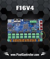
 
How do you normally power the board? Is it via the V2 or the EXT input?
If the V2 - run a wire from the Positive of V2 to the Positive of EXT power. It might be flipping to the other input.

Alternatively, you could remove the switch and solder a wire bridge in its place to hard-set it to one of the two inputs.
 
Normally it’s from the v2 which powers the right hand side of the pixels. So just run a wire from the positive of V2 to the positive of the EXT. What about the negative?
Removing the switch also sounds good as I always powered it from the v2 power but will try the first option as I’m not sure which of the existing solder point I would need to bridge.

Would either of these be the cause of the low voltage warning? I ask this as this year I am powering the board through an Anderson plug as I thought it would be easier to connect/disconnect. The cable on these plugs is much thicker than what I usually use which is just a 2 core x connect power pigtail. I thought the thicker cable would be better, but could it be that it is too thick? Not real great on understanding the electrical part of the hobby.
 
The cable on these plugs is much thicker than what I usually use which is just a 2 core x connect power pigtail.
The board itself draws very little current, only an amp or two at 12V if I recall.
So you don't need monster cable for it. It's the pixels that use the bulk of the power.

Normally it’s from the v2 which powers the right hand side of the pixels. So just run a wire from the positive of V2 to the positive of the EXT. What about the negative?
Negative is already connected on the board throughout.
The positive for the CPU is basically switched between the two inputs - this diagrammatically shows how the slide switch operates in that regard.

Code:
 V2 In +   >----o|
                 |o---- To CPU via Voltage switch
 Ext In +  >----o


 V2 In +   >----o
                 |o---- To CPU via Voltage switch
 Ext In +  >----o|

It's possible that the switch is not making contact with the center 'CPU' / output contact within the mechanism, at which point the suggestion of running via VExt won't work. You'd need to bridge out or replace the switch in this case.

Removing the switch also sounds good as I always powered it from the v2 power but will try the first option as I’m not sure which of the existing solder point I would need to bridge
If you look at the underside of the board, you'll see the switch has three PCB pins. These correspond to the diagram above - and physically the swtich is connecting the centre and top (for VExt) or Centre & bottom (for V2)
You'd just need to connect the centre and bottom to "hard set" that switch in the V2 position.
 
Back
Top