RGB LED Matrix on Roof

blueabacas

New elf
Joined
Aug 14, 2012
Messages
5
Hi Everyone,

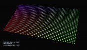
I'm hoping to get some feedback/advise on a RGB pixel matrix for my roof. I'm thinking right now it will be roughly 27 strings of 50 pixels at about 2 inch spacing. I've been reading over the forums and I've seen a few examples, but I just wanted to see if my layout/design looks generally good. I'm also thinking instead of standing upright due to high winds I'll try to mount the strings right along the angle of the roof (see image).

[attachimg=1]

Could I use a long thin coro strip which is scored to bend up to create an L, then cut holes along the strip and insert the leds through? So each led string would have it's own coro strip. Then brace the strip with a metal L bracket from behind.

[attachimg=2]


Here is where I'm at with the setup:

Lights: 27 x WS2811 50pcs DC5v
Would these work as good as the 2801 lights I've seen other people use? Would the 5v work ok for my layout?

Controller: 1 x ECG-P12R - 12 universes
Could I run 3 strings continuously per output (50 pixels/string, 150 channels/string, 3 strings = 450 channels)? Using 9 total outputs. How often would I need to inject power?

Power: Ray Wu 350w 5v
or a few of the smaller 60w 5v power supplies to inject down the line

Thank you for any help or suggestions!
 

Attachments

  • rgb_roof_tmp.jpg
    rgb_roof_tmp.jpg
    120.6 KB · Views: 413
  • rgb_roof_coro.jpg
    rgb_roof_coro.jpg
    22.4 KB · Views: 412

neilric99

Full time elf
Joined
May 20, 2010
Messages
295
Location
Irvine, the OC, CA
what is the viewing distance of the roof from the street, 2" is pretty high resolution from 50' or more, 3" is more common and saves on pixels and controllers
I like the idea of using coro strip to mount the pixels at an angle and allows you to keep them in line, whats the rake angle of your roof, dont want to make the pixels too vertical, having them lying down a little will give better coverage, they have a 120 deg viewing angle anyway.
 

Kaden

Pixels! I need more pixels!
Joined
Jan 10, 2012
Messages
724
Location
Gold Coast
I have plans to do something similar next year with 2811 strip (10ic/m) and use pvc piping for the frame.


The resolution wont be as good, but it wouldn't cost as much and should be easy enough to assemble and anchor to the roof.

Damn it! Now that I have though about it, I want to do it this year!
 

fasteddy

I have C.L.A.P
Global moderator
Joined
Apr 26, 2010
Messages
6,648
Location
Albion Park NSW
blueabacas said:
Could I use a long thin coro strip which is scored to bend up to create an L, then cut holes along the strip and insert the leds through? So each led string would have it's own coro strip. Then brace the strip with a metal L bracket from behind.

Yes you could use this method but it will be a lot of work. The suggestion i have is to use the 5050 5vdc strip which has 32 individually controlled pixels per metre, this will dramatically reduce your build time and give you the resolution your looking for, then just attach the strip to electrical conduit or lino floor partition and face towards the street

http://www.aliexpress.com/store/product/5m-led-digital-strip-DC5V-input-WS2801IC-256-scale-32pcs-IC-and-32pcs-5050-SMD-RGB/701799_465132154.html

Anyway just an alternate suggestion

blueabacas said:
Lights: 27 x WS2811 50pcs DC5v
Would these work as good as the 2801 lights I've seen other people use? Would the 5v work ok for my layout?

These will work well and in fact have more resistance to eklectrical noise and allow upto 20 metres between pixels, plus 1 less wire to solder. They have the same dimming qualities as the 2801.

Another pixel option is the sqaure pixel and instead you could just silicone the pixel in place on the coro, just another alternative to consider

Now take note that the 2811 is currently not offically supported by the ECG-P12R, that will change soon. But you can still do testing using the 1804 output code, but you will experience some flickering, good enough for testing. The update is very easy to do so that shouldnt really be a decising factor.


blueabacas said:
Controller: 1 x ECG-P12R - 12 universes
Could I run 3 strings continuously per output (50 pixels/string, 150 channels/string, 3 strings = 450 channels)? Using 9 total outputs. How often would I need to inject power?

With 5VDC you will need to inject between each string or strip, refer to the pixel connection diagram in the ACL ECG-P12R manual for further info on injecting

blueabacas said:
Power: Ray Wu 350w 5v
or a few of the smaller 60w 5v power supplies to inject down the line

What you could do is place your power supplies on either end of the matrix, as far as using a bunch of 60 watts compared to a couple of 350 watt power supply then i personally prefer to go the 350 watt as the cost per watt is far cheaper than buying a bunch of 60 watt Power supplies. But always keep a spare powers upply in case one fails.

Hope that helps
 

blueabacas

New elf
Joined
Aug 14, 2012
Messages
5
The viewing distance is about 58 feet and the roof is at about a 32 degree raking angle. I've been flip flopping between a spacing of 2" and 3". I like the 3" spacing since it gives a bigger more impactful matrix, but I wasn't sure it would be enough resolution. Good to hear that at this distance 3" could be fine.

I definitely like those strips Eddy and it would be a lot easier. Looks like those would have 160 pixels for a 5m strip. So I'm estimating the spacing between pixels to be roughly about 3.1cm or 1.2 in. This would give a pretty high resolution matrix and the price might be too high for my budget. Would these strips work if they needed to be cut and re-joined? Any other disadvantage with the strips vs. modules?

Did I give the wrong link to the WS2811 pixels before? Are those not IC? Would these be the right WS2811 pixel modules with IC : WS2811 5v IC?

I also see some of these pixel modules TM1804IC . Reading the info on the webpage it seems these have a wider bit depth - 24-bit which is maybe not necessarily worth it or noticeable. They are also 12v. Any other significant differences that would make these "better"?
 

fasteddy

I have C.L.A.P
Global moderator
Joined
Apr 26, 2010
Messages
6,648
Location
Albion Park NSW
blueabacas said:
I definitely like those strips Eddy and it would be a lot easier. Looks like those would have 160 pixels for a 5m strip. So I'm estimating the spacing between pixels to be roughly about 3.1cm or 1.2 in. This would give a pretty high resolution matrix and the price might be too high for my budget. Would these strips work if they needed to be cut and re-joined? Any other disadvantage with the strips vs. modules?

The other option especially due to the viewing distance is to use the 2811 10 IC per metre strip at $36 for 5 metres its hard to beat, now this strip is extremely cheap and seems to be good quality as well, out of the 18 2811 strips i got from ray this year I had 100% success with no failures

blueabacas said:
Did I give the wrong link to the WS2811 pixels before? Are those not IC? Would these be the right WS2811 pixel modules with IC : WS2811 5v IC?

No the link was correct, the link i gave was for the square type of pixel like this (the link is a 6803 IC but gives a closer view of the shape))

blueabacas said:
I also see some of these pixel modules TM1804IC . Reading the info on the webpage it seems these have a wider bit depth - 24-bit which is maybe not necessarily worth it or noticeable. They are also 12v. Any other significant differences that would make these "better"?

They are 8 bit like the 2801 and 2811, the 24 bit comes from 3 x 8 bit for each colour. I personally dont like the 180x series at 12vdc as they are set to run as constant voltage mode as opposed to constant current mode. LEDs are current devices so the best way for control is by using current control. Now more info on the differenceces between running 12Vdc and 5Vdc strings can be found here as there is a difference between the two.
 

blueabacas

New elf
Joined
Aug 14, 2012
Messages
5
All good options! I do like those 2811 10 IC per meter strips. Those would be a lot easier to mount.


Just to clarify these similar 2811 modules what are the main differences between them?
Comparing the info both are 2811, 12mm, DC5v, 50pcs
2811 DC5v $19 ID: 469177597 - higher rating - IP68 and wider beam angle 110-180. Item Type: Beads
VS.
2811 DC5v $18 ID: 564836955 - Item type: Led Modules


Thanks!
 

fasteddy

I have C.L.A.P
Global moderator
Joined
Apr 26, 2010
Messages
6,648
Location
Albion Park NSW
I see no difference between them, they are both 5vdc 2811 IC and IP68 rated. The only difference is the cost of $1 per string
 

blueabacas

New elf
Joined
Aug 14, 2012
Messages
5
Hi Everyone,
I made a more detailed plan of the wiring layout for the matrix and I wanted to run it by everyone to be sure I'm not missing something.

I plan on running three WS2811 50 pixel strings per output. My biggest questions are if I'm wiring everything correctly or most efficiently. I was thinking of putting a 3rd power supply on the far side to inject power without having to run too many wires across the matrix. I know the V+ shouldn't be bridged with the other power supplies, but is this an okay way to inject the power? Here's the diagram showing the layout:

rgb_matrix_layout.jpg

From my estimates I will need to run two separate 350w power supplies into the ECG-P12R. 27 strings of WS2811 50 pixels at 5v with 60ma max. This would be about 3amps per string right? (.06amps * 50pixels = 3amps) Using the two 350watt 5vdc power supplies feeding into the two banks on the controller splits up into 12 strings on one bank and 6 on the other bank since I'm injecting one of the 3 strings per output on the other power supply. Thus 36 amps total which is well below the 85% max load headroom. If I did all 18 strings that would put me above the 50 amp limit for the power supply I believe.

For powering the ECG-P12R I've referenced the ECG-P12R pdf guide and I just wanted to check if my assumptions are correct. Can I run two separate power supplies into the two banks and then still use the bridge connection on the K1 port?

For the 3rd power supply I will have a total of 9 wires running out for power injection. Will this be too many wires to physically connect back to the power supply (not in voltage, but actual connections) ?

If I used this 4 core 16 gauge wire would this allow me to combine some of these wires and then branch off in a Y multiple times so not all injections need to go all the way back to the source power?

As an example I could split off three injections from one source wire if the max distance is 3m and if the three strings are pulling a load of 9 amps max. 16 gauge wire shown in the chart is rated at 0.014 ohms per meter and a max load of 13amps.
3m x 0.014ohms = 0.042 ohms for 3m one way (Should this distance include the lights?)
0.042 x 2 = 0.084 ohms for total return circuit (but is part of the circuit in parallel?)
V = 9 amps (3 strings) x 0.084 = 0.756 volt drop

Would there be any concerns with the return voltage? Or how much load the wire is carrying?

Any other suggestions or help is greatly appreciated!
Thanks!
 

blueabacas

New elf
Joined
Aug 14, 2012
Messages
5
I just wanted to check back to be sure there aren't any issues with this layout posted above? This will be my first time doing this type of setup and any help is appreciated. Any issues with the 16 gauge wire or would it be better to get more head room and use the 14 gauge wire?

I was also reading on the forums of another option to run the power directly to the strings and bi-pass the controller (besides the power needed for the controller board). I'm not sure I prefer this method since it would skip the built-in fuses on the controller outputs which seems like a good safety precaution. Any thoughts on this method?
 

fasteddy

I have C.L.A.P
Global moderator
Joined
Apr 26, 2010
Messages
6,648
Location
Albion Park NSW
Looking at your diagram, it looks good and would be similar to the way I would connect this up (maybe do it next year) As far as the cable guage is concerned the 16 guage will be good for approx 13 to 14 amps and the 14 guage is good for approx 18 to 19 amps so each string will darw approx 15 watts for approx current of 3 amps at 5VDC, som depending on both how many strings will be connected to the cable and the distance away from the power supply will determine if you need to go down to 14 guage wire.

Now as far as connecting the P12R, you can connect up two seperate power supplies one for each bank, they dont even need to be the same voltages. Now with your 5VDC setup you would reference to example 1 on page 9 of the P12R ACL manual, the difference is that both terminals P00 and P13 will be fed from a seperate power supply.

Now the pixel connection can be connected either as option 3 or option 4 on page 11 depending on if you want both your supplies to go through the P12R or instead having just the 1 power supply for the P12R and the other power supply located on the other side as shown in your diagram.

Now the direct power connection method you are talking about is the same method that the ECG-P2 uses where as the power for the lights does not go through the controller but instead is supplied seperatly from the power supply. You can add your own inline fuse which are cheap anyway and for this method you can refer to option 6 on page 12.

It seems like you have a good basic understanding of your requirements already. So i hope that may help a bit more.
 
Top