Showstopper spinrer wiring diagram problems

Gerald

Apprentice elf
Joined
Jan 5, 2022
Messages
58
Hi
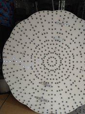
I am trying to populate the 541 SS spinner but having display problems with the sub models, I have wired if from pixel 1 center anti clockwise as shown in the wiring diagram from x lights
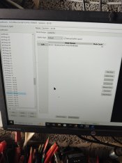
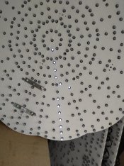
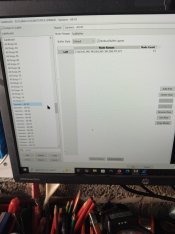
All of the individual rings light up correctly when testing output to lights from within x lights , however everything else is incorrect, the spinners for instance are not completely straight lines (as they should be) and other sub models do not display as shown in the model data window
If i alter the nodes to suit say the spinners , then the rings are out of sync!

I am surly missing something here but am at a loss as to how to fix it
 
My prop does not have the path printed as it was sourced from the UK, however I did download this pic and have followed it together with the xlights diagram
I have it on a Baldric controller on one port with power balancing and it is set to the channel start from xlights upload to controller as I have always done
 
When you say "If i alter the nodes to suit say the spinners , then the rings are out of sync" what change did you have to make? Maybe the detail there will be a clue.

Surely there is some fiddly difference with the wire path vs the model... I would check the start+end+string joints carefully against the marked nodes on the wire path above and make sure they are correct at the 100 boundaries (it's marked every 50) at least.
 
Unfortunately my prop does not have a printed path so I am to some extent working blind
When powered up all of the rings are lit fine but when I try the spokes as it were there are two or three out of line , I have checked these in X lights and they do light up as they are supposed to I.e. no 34 is 34 on the string, but they are completely out of place on the prop and the actual lit ones will not reach the desired hole to complete the spoke
It is almost as though the sub models have incorrect string numbers , however I doubt that is the case
 
Now, because the first part of the video is not there, I am not sure if you have the spinner approximately upside down or wound the wire the opposite way or have the video flipped. Which way was up? (It doesn't line up with the mounting fasteners, which could get confusing later.)

This is the innermost place where I see it going wrong, thought it might just be 2 swapped:
1783103321801.png

The staggering is somewhat consistent, so I would carefully review the part of the diagram here and see what your deviation is:
1783105848609.png
Finally, there may be some inconsistency with these areas since they vary by spoke.
1783105800056.png

Also I accidentally uploaded without the layout in it. Trying to make sure we are looking at an unedited model. With layout this time:


View: https://drive.google.com/file/d/13FLTK1knAKy4IHTnmCSMAg_Bpvz1PRQD/view?usp=sharing

View: https://drive.google.com/file/d/13FLTK1knAKy4IHTnmCSMAg_Bpvz1PRQD/view?usp=sharing
 
Back
Top