XerxesDGreat
New elf
- Joined
- Dec 26, 2020
- Messages
- 15
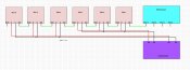
Hey all, I'm very confused as to the behavior of the display I'm in the first stages of testing. I have a Falcon F4V3 with two differential receivers. Currently, I'm running ~300px off port 1 on the controller (run A), 540 (6 x 90 px stars) off port 5 on one differential receiver (run B), and 450 (5 x 90px stars) off port 9 on the other (run C). Run A is a house outline and I have no problems with it. Runs B and C are very similar; the first three stars are powered by one port on a power distro board, and the remainder are powered by a second port. You can see the wiring diagram for B and C in the attached image.
The behavior is that only the fourth, fifth, and sixth stars on run B flicker sometimes (looks kinda like a twinkle). However, the strange bit is that the flicker doesn't occur when running the test pattern on the differential receiver, only when doing test patterns or actual sequences from the controller. I had a similar issue with stars four and five on run C, but bridged the ground between star four and star three and that seems to have resolved it; I did the same for run B and thought it resolved things, but that was when I was testing using the test pattern from the differential receiver; the problem returned when I ran the pattern from the controller.
Some details: the two differential receivers are connected to the controller via 100ft/30m cat6 cables; there is ~10ft/3m from the receivers to the first stars, ~25ft/7.5m between the receivers and the fourth stars, and about 4ft/1.5m between the remainders of the stars. I thought it could be a power issue so I upgraded the long cable on run B to 12awg (from 14awg) and that seems to have not made any difference.
What else could cause the difference in behavior between the test pattern from the receiver and the controller? My understanding is that, since all the stars connected to one differential receiver are all on the same port they would all be affected if it's a connection issue between the controller and the receiver. What else should I test? Thanks in advance for the guidance!