Testing wires

Binkles

Full time elf
Joined
Dec 11, 2012
Messages
263
Location
Baldivis
Is it possible to test if a wire is the same at both ends?


Ie I've got pixel, wire, pixel wire pixel wire.... Some are covered by shrink tubing, so I can't be sure that I have the correct wires soldered together.

Pretty sure I do though...

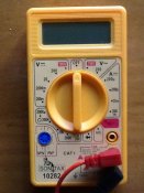
I have this multimeter (cheap I know) but wondering if there is a setting on it that could help.

Thanks
 

Attachments

  • ImageUploadedByTapatalk HD1361488842.346598.jpg
    ImageUploadedByTapatalk HD1361488842.346598.jpg
    91.3 KB · Views: 26
When testing the strings this is what you should find.

+V and ground will have a circuit from one end of the string to the other as these are connected in parrallel. What you have to confirm is what is the +V and the ground,

The data is connected in series so you shouldnt get a reading between the beginning and the end of a string , this you can confirm as being your data wire.

You do not want to get the +V mixed around with data or ground or damage will occur to the string.
 
Couldn't you use the continuity function, on your multi meter?

I've never tried on string of pixels, but I've tested numerous other wires, to make sure of no internal breaks.
 
Robert said:
Couldn't you use the continuity function, on your multi meter?

I've never tried on string of pixels, but I've tested numerous other wires, to make sure of no internal breaks.

i use the continuity tester myself
 
Binkles said:
Which setting is that one?
Would usually have a little speaker icon on it - as it'll beep when it senses continuity..

Can't seem to see one on that multimeter, so may not be an option (most multimeters I've seen, including $10 ones from ebay seem to have it though!)
 
That meter does not appear to have "beep" setting but you can use the resistance setting which is the same but without the beep.
Set the dial to the 200 that is to the left of the 6 o'clock setting. If you touch the probes together the display should show 000. Now connect one probe to a wire you want to identify and then touch the other probe to the wires you want to identify, when the display goes to zero you have the probes on the two ends of the same wire.


Make sure you don't have the power connected when doing this.


Jon
 
Thanks for the methods.

I had wired two wires wrong. The Death Star now looks like this.

http://vimeo.com/60249704
 
Very much so. Now trying to work out mini star. 5 modules in a star shape.

I'm correct in that + and ground don't have to be in series?

As you can see from my expert cad drawing.

Yellow are the three wires going in, orange is going out, the orange in the pic would just be data, though I guess I could feed the + and ground through to it....

The aqua line is data, blue are the 3 modules.

Trying also to work out how to mount it.
 

Attachments

  • ImageUploadedByTapatalk HD1361581795.312986.jpg
    ImageUploadedByTapatalk HD1361581795.312986.jpg
    58.6 KB · Views: 10
Back
Top