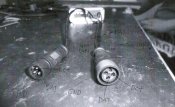
What pin is what???

richardd

Full time elf
Joined
Jan 3, 2011
Messages
347
Location
Geraldton
G'day

I purchased the following lights from ray http://www.aliexpress.com/item/50nodes-C7-DC5V-5050-SMD-WS2811-LED-technicolor-pixel-waterproof-RGB-full-color-in-BLACK-color/1704995268.html Now I have a problem as they are sealed I don't know what pin is what.

IMG_0084.jpg


I'm assuming that the single pin on top is data as I don't get continuity but I don't know if the left pin is power of ground. Can I please get a little help?

Thanks and cheers
Richard
 

AAH

I love blinky lights :)
Community project designer
Joined
Dec 27, 2010
Messages
4,191
Location
Eaglehawk
It might be like the attachment below.
The data wire is easy to work out as a multimeter will give you continuity from 1 end to the other on the other 2. Working out which is the + and which is - from there is anyones guess.
 

Attachments

  • Technicolor_n.jpg
    Technicolor_n.jpg
    25.1 KB · Views: 45

BundyRoy

Dedicated elf
Joined
Apr 9, 2014
Messages
1,026
This is what I would do, but I am happy for others to criticise my technique if it is poor form. First I would email Ray and ask him. Then I would cut the wires between the first and second pixel. This way if it is wrong you only lose one pixel not the lot if you get it wrong (or do you only lose the first anyway). Then I would give it a crack based on rays advice (or a guess if no feedback or not prepared to wait). If it works all good, join wires back up with heatshrink. If it doesn't then it is the other way around. Chuck out first pixel and join wires back up. Good to go. Worst case scenario one pixel down on one string.

I would wait for confirmation of my technique from others though before giving it a crack. There may be other shortfalls I didn't think of.
 

andrewa

Full time elf
Joined
Dec 22, 2012
Messages
262
Location
Frankston North, Victoria
I had the Same problem with the same pixels. I had ray send me the following diagram
wiring.jpg
They are wired up as per the left plug and not the right plug.


The diagram on the right is wrong, but wiring up as per the left worked for me


It is the opposite to all other pre wired I have got from ray


Andrew
 

AAH

I love blinky lights :)
Community project designer
Joined
Dec 27, 2010
Messages
4,191
Location
Eaglehawk
Waiting to get info from Ray will save you from destroying them for this year. The info should get back to you by about February.
Providing your soldering and heatshrinking skills are adequate I'd go with checking with a mutimeter to see if the +ve and -ve appear to match the picture i posted. If they do then chop 2 out of the 3 wires (no need to chop the 3rd). Try it and hopefully it will work 1st go. Solder the 2 wires back together.
 

BundyRoy

Dedicated elf
Joined
Apr 9, 2014
Messages
1,026
YAGOONA LIGHTS said:
this is why I solder my own plugs on ::)

Was just thinking about this. You are still relying on the colour of the wires to determine the +ve/-ve aren't you as there is still no definitive way to test it. Or can you see a code where the wires solder onto the first pixel.
 

dale82

Senior elf
Joined
Nov 19, 2010
Messages
581
Location
Kingaroy
Bundy you can use a multimeter to determine what wire correlates with what pin, So the colours of the wires become irrelavent. as I have found out, the colour wire can change from Ray.
 

richardd

Full time elf
Joined
Jan 3, 2011
Messages
347
Location
Geraldton
I sent Ray an email and the just reply with the same diagram as AndrewA sent me. Finger cross I don't blow up the set
 

BundyRoy

Dedicated elf
Joined
Apr 9, 2014
Messages
1,026
dale82 said:
Bundy you can use a multimeter to determine what wire correlates with what pin, So the colours of the wires become irrelavent. as I have found out, the colour wire can change from Ray.

I know what you're saying Dale. I more meant that if you got a sealed set of pixels with no plug and only wires coming out of the first pixel you would still not be able to tell what wire was +ve/-ve. I'm guessing you must be able to see the codes on the first pixel to determine which wire is which.

Good luck Richard. Fingers crossed.
 

ԆцряєсϮ

Senior elf
Joined
Dec 24, 2011
Messages
503
Location
Botanic Ridge
You know what wire is what on the wire between the first and second pixel so get a pin, stick it into the +ve wire coming out of the first pixel and use your multimeter to buzz it through. Once you know which is the +ve you'll also know which is the -ve
Remove the pin and your done...... no cutting or soldering required :D
 

damona

Full time elf
Joined
Oct 23, 2013
Messages
296
Have we got a final answer on this? Someone willing to offer a 3 pin drawing and confirm its correct.
 

battle79

Full time elf
Joined
Dec 8, 2012
Messages
465
Location
Chirnside Park, Victoria, AU
The final answer is that each set of pixels you get could have different colours and pin configurations. I've had several myself. The only to be sure is as ruprect said, you get a pin and pierce the insulation at a point where you can tell what the wire is, and then test between that spot and the end of the plug.

For strip you can hopefully do this with a wire before it goes into the sleave. For pixels, find one where you can read the writing on the circuit board to know which wire is which.

Regards,
Rowan
 

fasteddy

I have C.L.A.P
Global moderator
Joined
Apr 26, 2010
Messages
6,648
Location
Albion Park NSW
It was left out of the ACL101 manual because consistency can not be guaranteed when it comes to wire colours as there is no set standard
 
Top