Wiring & modelling query (diy panels)

Pavle

Rank updated… 2 season veteran
Joined
Nov 7, 2020
Messages
190
Location
Sydney
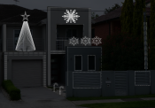
I'm planning on using a series of panels to outline my house and provide more real estate for pixel coverage.
What would be the best way to layout the wiring plan and then what would be the best way to model this in xLights?

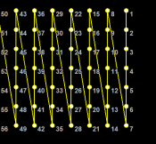
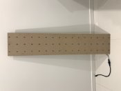
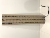
I've gone ahead and cut a prototype and fitted it with a string of 48 pixels, wiring it along the long edge (3x16) for the purpose of getting a visual on how it would appear, as well as to ascertain if it's a feasible proposal and it looks like it's the going to be the way I want to proceed.
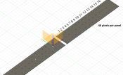
PixelColumn.png

In xLights I've set it up as a matrix with 3 strings by the appropriate nodes/string and laid it all out (virtually) over my house facade and I am pleased with how sequences are being rendered, the question is how do I go about wiring for this considering each panel will be limited to 2400mm length and I will have sections with 2 and 3 panels joined together on the short edge (240mm) - is the matrix model correct or is there a better solution?
(there will be panels running both horizontal and vertical, but the same concept will apply joining at the short edge)

Ideally, I want each panel to connect at a single point to the next panel to facilitate easy removal and storage.
in my example, nodes 1 to 48 are on panel 1 and nodes 49 to 97 on the next panel.
I want xlights to display nodes 1 to 16 then 49 to 65 as string 1 and nodes 17 to 33 then 66 to 82 as string 2 and so forth.

Hopefully this makes sense?
 
Last edited:

Mark_M

Annoying Elf
Joined
Dec 30, 2018
Messages
914
Location
Christmas Light world
I've done my own icicles as a matrix for above my garage:

These use actual icicle strings.
You can see the panels split apart with one connector.

View: https://youtu.be/kDdljeNrDlM?t=22


My drop layout looks like this:
icicles.PNG


However; I remember talking to someone in my area and he mentioned that Xtreme Sequences (Ron Howard) has a method to use standard bullet strings in an icicle form.
In icicle form, the whole outline can be one model and there's a single point to chain each panel from.
This is the video:

View: https://youtu.be/2xda1HZNa0g?t=277


I have tried this in xLights with 3 per drop:
icicles5.PNG

You need to select "Alternate nodes" and have 3 nodes in place.


Then I thought that the icicle model doesn't work well around a house outline.
Keith said in a beginner seminar that the "poly line" model could be made into icicles.

So I tried, YES!.
Make a poly line, set drop pattern to 3 and alternate nodes.icicles6.PNG
Node layout should look the same as image above (1, 3, 2). (For some reason there's no wiring view for poly line?)

You can always separate the models out if you want, or sub model one big model.
 
Last edited:

Pavle

Rank updated… 2 season veteran
Joined
Nov 7, 2020
Messages
190
Location
Sydney
Awesome, that sounds almost identical to my application. Will give it a test soon
 

Pavle

Rank updated… 2 season veteran
Joined
Nov 7, 2020
Messages
190
Location
Sydney
I've followed both your example @Mark_M and the linked video from Ron Howard and unless I am missing something, the icicle method with alternate wiring adds a level of complexity that possibly isn't required for what I need - Please correct me if I am wrong as I am only utilising the xlights render to form any conclusion. I will try and set up a real world test using two panels in the next week or two.

Poly Line method
Horizontally, this was easy to setup and works as expected. Switching to vertical proved to be slightly more difficult.
The model was a pain to 'square up' and it wanted to jump to a staircase type layout.
I was able to get it right, just took a lot of precise mouse movements and maximum zoom in
I had to create sub-models for each line then add to a group as per the instructions for it to function

PolyLineConfig.PNG
PolyLinePreview.PNG

Matrix method
Setting up 3 panels using matrix and aligning them alongside my 3 'icicle, poly lines' sections, then marrying up the node/string count was a more user-friendly setup and as far as I can tell offers the same result?
There is no requirement to sub-model, I just added them to a group and setup my preferred starting location
Switching between horizontal and vertical is assisted by the built-in capabilities within xlights so this is another positive

MatrixConfig.PNG
MatrixPreview.PNG

Here is a short house preview export to see the comparison: HousePreview

The wiring view for the matrix doesn't require alternate nodes and I believe this will help me due to positioning of my control panel.

MatrixWireView.PNG

Any reason not to go this way?
Perhaps there is an effect(s) that won't be suitable in this configuration?

Thanks
 

Mark_M

Annoying Elf
Joined
Dec 30, 2018
Messages
914
Location
Christmas Light world
I've followed both your example @Mark_M and the linked video from Ron Howard and unless I am missing something, the icicle method with alternate wiring adds a level of complexity that possibly isn't required for what I need
Reason you may want the icicle method is so there is one connector joining between panels of pixels. To xlights it can be one big model for all sections too.
Like my icicles as a matrix, to xlights it is one model. But in reality it breaks into 4 panels.
Reason for alternating nodes is because I assume you are using a string of pixels. The spacing between is not enough for a drop of 3 and back to the top.

I can see from your photo that you've zig-zagged the poly line 3 times. This is not what I meant.

Draw 1 line on screen and select 3 drop. It will turn from a single line into a grid 3 pixels in height. It will be perfectly square.
Alternate nodes makes it skip up/down nodes, this is useful because you do not have large spacing between nodes.

The wiring view for the matrix doesn't require alternate nodes and I believe this will help me due to positioning of my control panel.

MatrixWireView.PNG

Any reason not to go this way?
Doing the matrix like you've shown above has 3 runs of pixels zig-zagging, if you need to cut that into sections for 2 panels then you'd have 3 connectors to add between. You've mentioned that one panel is 48 pixels, so I assume this image is 2 panels of pixels.

If this is the layout for 1 panel of pixels, then the next would connect with no problem. The next panel after would be another matrix model.
[Example] We'll say you have 3 panels of these pixels to make a column. Within xLights it would have to be 3 models. That means you'd sequence it as a group.
Poly-line method still has data start at one end and finish at the other like this image above and xlights doesn't have to care were the connected panels cut to fold down.


Big 'But' on this one;
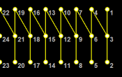
Change you matrix to zig-zag the other way. Then you get the benefit of the poly-line method with 1 data point to connect the next panel onto.
This still means that each block (straight run) of panels will be 1 model. However, You'd get a second model if the matrix continues around a corner.

Perhaps there is an effect(s) that won't be suitable in this configuration?
How you layout your nodes does not change how effects are applied. xLights looks at the pixels on screen and layers the effect over top, the preview just needs to be correct with pixel layout.
 
Last edited:

Pavle

Rank updated… 2 season veteran
Joined
Nov 7, 2020
Messages
190
Location
Sydney
Thanks for the explanation Mark and your attempts to assist, it's most appreciated.

I am definitely not quite understanding, particularly about the 1 data point to connect the next panel - this is exactly my goal so important to get it right.
In my matrix sample that I have cut on a CNC already, I had a string of 48 pixels handy, that's why I went with that, plus it worked out nicely to give me 3 x 16 on the panel - I start at a corner, pushed 16 along the long edge and then moved to the centre, travelling back down 16 across and back up 16 - this gives me a data entry at one end and data output at the opposite end - this is also how I mapped it in xlights so my assumption was it would provide a single data point.

When I move into doing the final panels, my plan would be to use 2400 x 1200 sheets and that will give me individual panels of 2400 x 250 (96 pixels per panel). My longest vertical column is 6710, this would consist of 3 panels (2 x 2400 and 1 x 1910 totaling 267 pixels). My widest horizontal is 3970.

Here is a sample of my draft layout:

HousePreview.PNG

I will be placing an order for the pixels in the next few weeks and I'll most likely be ordering custom strings to suit. Just need to sort this out before I hit go.

7E1ED611-E12D-434B-B7AD-39BD47D2B609.jpeg 32D521C9-F4B9-48C6-928A-4D8DB4702F34.jpeg
 
Last edited:

Mark_M

Annoying Elf
Joined
Dec 30, 2018
Messages
914
Location
Christmas Light world
I am definitely not quite understanding, particularly about the 1 data point to connect the next panel - this is exactly my goal so important to get it right.
In my matrix sample that I have cut on a CNC already, I had a string of 48 pixels handy, that's why I went with that, plus it worked out nicely to give me 3 x 16 on the panel - I start at a corner, pushed 16 along the long edge and then moved to the centre, travelling back down 16 across and back up 16 - this gives me a data entry at one end and data output at the opposite end - this is also how I mapped it in xlights so my assumption was it would provide a single data point.

View attachment 16787 View attachment 16788
Now that I see you entire house, I see that you're lucky to have a flat exterior.
Problem with matrix model is that you have to make multiple models if it goes around a corner, and then those don't align perfectly. Poly-line bends and with drop adjusted its perfectly square.

Your models are going to be 1 matrix for horizontal and verticals, so we don't need to go around bends! We'll keep the matrix model.

My longest vertical column is 6710, this would consist of 3 panels (2 x 2400 and 1 x 1910 totaling 267 pixels). My widest horizontal is 3970.
This is the mention where I suggest a different wiring layout. Thankyou for an image to use.

We'll imagine this is the 3 panels acting as 1 matrix.
With this wiring layout it will be 3 matrix models in xlights. That means you'll have a lot of fun getting them perfectly aligned to each other in the preview and you'll be sequencing them in groups.
3_matrix_panels.PNG

If you make it 1 model with this wiring layout then you'd need 3 connections at each panel join.
3_matrix_3connectors.PNG


This is where I would be going to poly-line to make square icicles. But this will now be irrelevant since you pixels look to have little cable between nodes....
Spoiler content hidden. Log in to see this content.


So plan B:
matrix_different_zigzag.PNG
Adjust the matrix to a wiring pattern like this. You'll get the benefit of 1 xlights model and there is one connector between panels (black dot is connector and panels joining).
different_zig_zag.PNG


I still think poly-line is better because it can bend around a roof line but the front of your house looks to be fairly 2D so this shouldn't be a problem.
 

Pavle

Rank updated… 2 season veteran
Joined
Nov 7, 2020
Messages
190
Location
Sydney
Thanks for the explanation Mark and the pictures certainly help.
I'm going to put together 2 pieces of the panels, setup both methods in xlights and run through some sequences and see what the results offer.

Just to clarify:

I can see from your photo that you've zig-zagged the poly line 3 times. This is not what I meant.

Draw 1 line on screen and select 3 drop. It will turn from a single line into a grid 3 pixels in height. It will be perfectly square.
Alternate nodes makes it skip up/down nodes, this is useful because you do not have large spacing between nodes.

How should this be configured?
If I draw a horizontal poly line, left click starting point, left click finish position then esc to clear the next point, select 3 drop and then adjust # Nodes to 96, I get a perfectly looking square result that I can see would suit this application.
If I draw a vertical poly line, left click starting point, left click finish position then esc to clear the next point, select 3 drop and then adjust # Nodes to 96, I get a hot mess of a single line like this:

VerticlePolyLine.PNG

If the way I am doing it is correct, but beyond the capabilities of this model type, what would you suggest?

Adjust the matrix to a wiring pattern like this. You'll get the benefit of 1 xlights model and there is one connector between panels (black dot is connector and panels joining).

Is this the correct configuration for Plan B matrix?

AltMatrixConfig.PNG

Gives me this:

AltMatrixWireView.PNG

Thanks again,
 

Mark_M

Annoying Elf
Joined
Dec 30, 2018
Messages
914
Location
Christmas Light world
How should this be configured?
If I draw a horizontal poly line, left click starting point, left click finish position then esc to clear the next point, select 3 drop and then adjust # Nodes to 96, I get a perfectly looking square result that I can see would suit this application.
If I draw a vertical poly line, left click starting point, left click finish position then esc to clear the next point, select 3 drop and then adjust # Nodes to 96, I get a hot mess of a single line like this:

VerticlePolyLine.PNG

If the way I am doing it is correct, but beyond the capabilities of this model type, what would you suggest?
That one I actually don't have a clue on, I know the icicle model can adjust the drop end location (including sideways) so it's interesting to see it hasn't been implemented to poly-line icicles.

Is this the correct configuration for Plan B matrix?

AltMatrixConfig.PNG

Gives me this:

AltMatrixWireView.PNG
That looks good.
 

Pavle

Rank updated… 2 season veteran
Joined
Nov 7, 2020
Messages
190
Location
Sydney
So plan B:
matrix_different_zigzag.PNG

Adjust the matrix to a wiring pattern like this. You'll get the benefit of 1 xlights model and there is one connector between panels (black dot is connector and panels joining).
different_zig_zag.PNG

Now that I have my F16V3 powered up and configured, I put this through some tests tonight and the layout depicted above is giving me mostly accurate results. Here is a short clip to demonstrate how it's rendering on the model - Video
This is 2 strings of 48 pixels joined together and I've only got 48 illuminated by way of a sub model, but the join is in the middle of my panel to illustrate how multiple panels would connect.

I now understand why the poly line would be the preferred method and how my original wiring plan was incorrect. If xLights can eventually offer a solution that would use the poly line, that would be ideal

The only trap is my horizontal panels need to be setup as vertical under the model direction and vertical setup as horizontal - I still don't know if this will eventually cause me problems when sequencing, however the tests I've done so far have gone as expected and I've used a variety of sequences and they run the same on the physical panel as they show within xlights.

I will be moving forward with my pixel order in the next few days so if anyone has any final input to this plan, please let me know.
 
Top