Wiring Pixels to Falcon F16V3

HertzSwift

Apprentice elf
Joined
Sep 16, 2019
Messages
89
Location
Perth
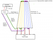
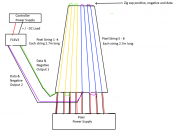
Tha'ts a good point, I initially grouped them into lengths of 3 strings per output because of the limitations of the F16V3 outputs. Since the power supplies are now external to that, I can do more, 9 outputs of 4 strings in the plan then!

In regards to the types of power supplies, best to over compensate than under compensate. With 1065 watts, I'll probably need 3 of the HLG units to run this setup.
 

i13

Dedicated elf
Joined
Jul 5, 2013
Messages
1,172
That's true about the power supplies. You may well find that the pixels draw less than I calculated but another power supply can be used for other display items in future and it is sensible to have a spare because they can fail.

Keep in mind when adding up the total power that you don't want to exceed 2400 watts on a single household power outlet. Taking the power supply efficiency (91%) and power factor (0.95) into account here, you've used approximately half of that with the tree on full brightness white.
 

HertzSwift

Apprentice elf
Joined
Sep 16, 2019
Messages
89
Location
Perth
Ok tree plan 6 has been updated. It's modified to have 4 strings connected per output. I've also modified the wiring slightly, halving the number of power supply inputs and instead incorporating them into the zig zag connection at the top of the tree. This would mean that the distance between each power supply connection is 5.54m (2.77 x 2)

If the wiring between the pixels if 18 AWG which is rated at 7.5amps, and each string is rated at 3.3amps, 3.3 x 2 =6.6 amps, the cabling will be sufficient.

How does this plan look?
 

Attachments

  • tree 6.png
    tree 6.png
    73.3 KB · Views: 34

i13

Dedicated elf
Joined
Jul 5, 2013
Messages
1,172
The power layout in your previous diagram was better than this one; it just could have had a few redundant cables removed. Data should be zig-zagged (and sometimes you'll connect the negative alongside it) but it is better for the power (including the negative) to be connected at the base of every strand regardless of what happens with the data. If you want two strands to share a power cable, it is better to connect them both to the same power cable at the base of the tree. The reason for this is that voltage drop happens over distance. If the current needs to travel all the way up and down the tree in order to reach the lowest pixel on some of the strands, there will be more voltage drop than if that strand was connected to the power at the base. In other words, from a power perspective, in your diagram here, the furthest pixels from the power injection points are 108 pixels away. In your previous diagram, the furthest pixels from the injection points are 54 pixels away. Data is directional but power isn't. Having said all of this, your current diagram might work fine at 30% brightness.

On the topic of voltage drop, I don't expect this to be a problem at 30% brightness when you're building for 100% but there may be scenarios in which you need to use thicker cable than the minimum thickness that can safely handle the current. Voltage drop is due to resistance in the cables. Thicker cables have lower resistance. Depending on the length of the cables, they might have enough resistance to cause incorrect pixel colours due to voltage drop even though they can safely handle the current.

I would not trust the seller to supply pixels with actual 18 AWG wire between them. It might be a bit thinner than 18 AWG but still better than the default. Powering each strand at the base of the tree should help compensate for this because the wire between them will only need to carry the current for a maximum of 54 pixels.

Your diagram will need to have a separate positive bus bar for each power supply but they can share the same negative one. One 480W power supply might be enough for 30% brightness. Hopefully someone who reduces power supply capacity with brightness can chime in. My thinking is that it is a good idea to have two of them in case one fails. If you have two then you may as well use both and share the load. If one fails then your backup plan could be to use the remaining one to run the whole tree at 30% brightness. If you're planning to add more 12V display items in future then there's nothing wrong with having spare power supplies now.
 

HertzSwift

Apprentice elf
Joined
Sep 16, 2019
Messages
89
Location
Perth
I'm going to be designing the unit to work on 100% white brightness, don't want to be replacing fuses or reseting circuit breakers. I'll be taking the safe road with power supplies and e using more than needed, for the reasons you've mentioned.

I was trying to minimize the amount of cabling required, it's getting very busy down at the base. But voltage drop is certainly something I had thought about, but thought I could design myself out of it. Sounds like I might be getting myself into some undesirable results, so I'll return the power how it was before. And not 18AWG from chinese sellers is also another unfortunate truth.

I've also removed the negative cables zig zagging with the data cables.
 

Attachments

  • tree 7.png
    tree 7.png
    72.3 KB · Views: 33

i13

Dedicated elf
Joined
Jul 5, 2013
Messages
1,172
That should work. You might (or might not) want to zig-zag the negative with the data at the top of the tree. Doing so would provide a more consistent reference for the data but it creates negative loops. A more consistent reference can prevent flicker but negative loops can cause flicker. There's no perfect answer for whether or not to do that and you're likely to be fine either way.

It is okay to halve the number of power injection cables and power two strands per cable if the cables can handle it. The way to do it is to connect the power from the injection cable to both strands at the base of the tree. Ray Wu sells T splitters that are designed for this purpose. You'd power the first strand on its own but then the the others can have a T splitter that carries the data from one strand to the next whilst also powering both strands.
 

HertzSwift

Apprentice elf
Joined
Sep 16, 2019
Messages
89
Location
Perth
Just an update for those who helped me, your advice isn't falling on deaf ears! I'm currently working off Tree 8 plan, its similar to plan 7 except I'm only using 2 channels on the Falcon F16V3 for the mega tree, 16 strings per channel. (848 lights per channel)

Tree isn't completed yet, but it's getting close, I tested all the pixels last night with a pixel teste., making sure inputs and outputs are all connected properly, so far all good. I'm starting to work on the mega tree power supply now.


treee 2.png

20210716_104332.jpg
 

Pavle

Rank updated… 2 season veteran
Joined
Nov 7, 2020
Messages
190
Location
Sydney
Nice job, you're making great progress.

What are the power distro boards you're using?
 

HertzSwift

Apprentice elf
Joined
Sep 16, 2019
Messages
89
Location
Perth
Those 3 PCBs are DC controllers from Hanson Electronics. I'll be using some of my excising dump RGB elements from my previous year display, in this years display I'm not converting my entire display to pixels this year, too expensive and too much work!

The controller enclosure has been powered up and configured in xlights, performing some routine tests of the Falcon F16V3 and the DC controllers, all working as it should be...so far...I haven't even looked into how to actually program a show yet, I'm focusing my attention on the hardware, that time will come.
 

i13

Dedicated elf
Joined
Jul 5, 2013
Messages
1,172
What frame rate are you sequencing at? Exceeding 680 pixels per output on the F16V3 (assuming no expansion board is attached) means that its maximum frame rate will be below 40 frames per second. For reference, 40 frames per scond is achievable with 680 pixels per output and 20 frames per second is achievable with 1024 pixels per output. 848 pixels per output will be somewhere in between. I suggest making a couple of spare strands for the mega tree. A dud pixel can stop passing on the data to the pixels after it. This could be half of the tree. You're already using connectors so having spare strands would make this a quick fix.
 

HertzSwift

Apprentice elf
Joined
Sep 16, 2019
Messages
89
Location
Perth
I have no idea what frame rate I'll be sequencing at, I have seen and played around with the animation at 20fps, looks ok to me. Is the difference between 20fps and 40fps just a smoother transitions between pixels? What do you use/or prefer?

What setting do people generally go with? To be honest I didn't even consider what frame rate I'll be using when building the mega tree, I've watched over a dozen, easily, mega tree videos on youtube and read articles here, and I have no memory of them taking about FPS, I don't think the Falcon controller instructions mention it either, so this comes as a real surprise to me. They all seem pretty focused on the amount of pixels being able to run out of a single port.

Couple of spare strings is a good idea.
 

i13

Dedicated elf
Joined
Jul 5, 2013
Messages
1,172
I use 40 frames per second but 20 seems to be more common. Keep in mind that exceeding 680 pixels on any one output will reduce the frame rate of the entire F16V3. I suggest making an additional sequence at 40 frames per second, aligning some effects with the music and seeing whether it looks any better to you.

Why I use 40 frames per second: I was once tested to see how quick my eyes and ears were. There was a little machine with two LEDs on it. They would both flash and I was tested on whether I could tell which one flashed first. The time between the flashes was gradually reduced. I was similarly tested with a pair of headphones that made a click noise in each ear. The idea was that there should be a point at which I could no longer tell which of the flashes/clicks was first. In reality, I maxed out the system which could only go down to a 5 millisecond difference. 20 frames per second is one frame every 50 milliseconds so maybe that's why I am not satisfied with it. I find the 50 millisecond sequencing grid to be too limiting and I can't get the effects to align closely enough with the music.

There are other considerations when choosing a frame rate. If you're using a computer that is slow to render the effects then reducing the frame rate will speed up the rendering. It also reduces the file sizes which may be a consideration if you're using something like Falcon Player. I did a rendering time comparison for one of my sequences in this thread: https://auschristmaslighting.com/threads/13383/

The timing in the display will never be perfect due to very slight delays in the signal getting out to the pixels.
 

djgra79

My name is Graham & I love flashing lights!
Global moderator
Generous elf
Joined
Dec 27, 2011
Messages
2,163
Location
Cranbourne West
A couple of years ago I started switching from 20 to 40FPS. I noticed it particularly with very fast moving or strobe type effects were much smoothly, and yes it also means you can get the timings just the little bit closer to precisely on beat (maybe being a DJ I notice these things a little more than others!)
But i13 raises a good point about controller pixel count limitations with the higher frame rates, so I'll need to do some checks myself this year to ensure I'm within said specs (my first year using the F16v3, upgraded from v2)
 
This thread is very old. An answer might not be needed anymore.
Top