Relay Output
Sometimes you need a DC controller channel to turn something on and off, but you need electrical isolation. Here's how to drive a relay from a DC controller output.
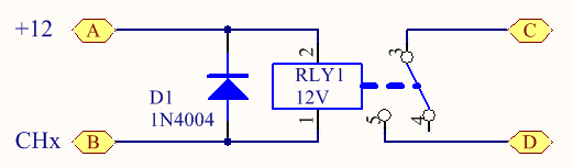
Schematic
Below is a schematic of the relay and the catch diode. When you remove power from the relay coil, it actually gives a big (reverse polarity) pulse of power back down the wires. The diode is there to short out this unwanted spike. Without the diode, the transistor (in the controller) would be damaged by the spike.
In this example, the relay contacts (marked C & D) are closed when the channel is on.
We are also assuming that the DC controller is being used with a 12V DC power supply. For other power supply voltages, you will need to choose a relay with a matching coil voltage.
In this example, the relay contacts (marked C & D) are closed when the channel is on.
We are also assuming that the DC controller is being used with a 12V DC power supply. For other power supply voltages, you will need to choose a relay with a matching coil voltage.
Parts
So, you need a single pole relay and a diode. The relay can be something like the Altronics S4160A or Jaycar SY4061. The pictures below are for the S4160A relay, but I believe the SY4061 is the same pinout. The diode is a common 1N400x (1N4001 .. 1N4007) type.
Soldering
You can solder the diode directly to the relay's coil terminals.
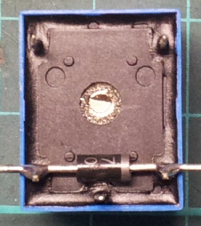
Get yourself a relay and diode:
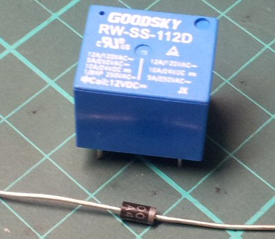
The relay has 5 terminals; 2 are the coil and the other 3 are the contacts:
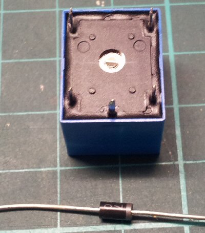
Place the diode so that it rests against the coil terminals as shown:
Solder each junction of the relay terminal and diode leg:
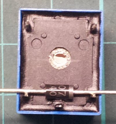
Carefully snip off the rest of each diode leg:
Get yourself a relay and diode:
The relay has 5 terminals; 2 are the coil and the other 3 are the contacts:
Place the diode so that it rests against the coil terminals as shown:
Solder each junction of the relay terminal and diode leg:
Carefully snip off the rest of each diode leg:
Connections
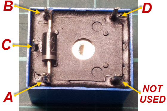
Referring to the last image above, connect '''A''' to the channel V+ on the DC48 and '''B''' to the channel that you want to use to trigger the archway. The '''C''' and '''D''' terminals are the NO (Normally Open) contacts and wire to the device you want to control.
Make sure you program that new relay channel to be either fully on or off, not dimmed or faded.
Make sure you program that new relay channel to be either fully on or off, not dimmed or faded.
Multiple Voltages
Controller Basics
Most DC controllers use the same basic principles. They have a data input (DMX, LOR, etc), a DC input and one or more channel outputs. The data input is beyond the scope of this article, so is not represented in the diagrams.
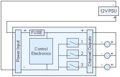
In the diagram below, you'll see that the power +ve input goes through a fuse, then to the electronics and the channel +ve terminal. Please note that not all DC controllers have a fuse on the board. Either way, the power +ve input goes to the channel +ve terminal(s) without being switched.
Now, look at the power -ve input. You'll see that it also goes to the electronics, as well as the output switching transistors (MOSFETs usually), shown here as simple switches. As you can see, it's the -ve power that is being switched on and off under control of the electronics.
Example 1
This is how a DC controller is most often connected. The same power supply is used to power both the controller's electronics and the attached lights.
Example 2
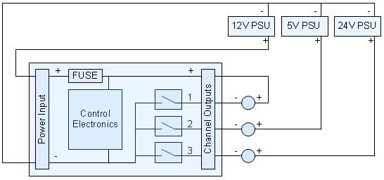
For mixed voltage switching, we can use the -ve wire switching to our advantage. Check the diagram below. All of the power supplies have their -ve terminals connected together and go to the -ve power input terminal on the controller. In this example, the 12V power supply is powering the controller electronics as well as the 12V lamps connected to output 1. The 5V and 24V power supplies are only supplying power to their respective lamps.
Example 3
But what if you your controller needs 12V to operate, but you only want to use 5V lamps (or strings) on the outputs? No problem. In the diagram below, you'll see that the 12V power supply is only supplying power to the controller electronics and that the 5V one is supplying power to the lamps.

Example 4
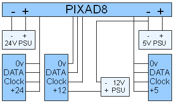
The following diagram shows how to connect a third power supply to a PIXAD8. You'll see 5V and 24V power supplies hooked up in the usual way. The 12V power supply could be to drive some 1804 pixels or 6803 strip. The +12V wire from the third type of strip / strings goes to the +ve terminal of the +12V power supply (via a fuse, not shown). It does not connect to the 4 pin pixel connector on the PIXAD8 at all. The 0V of the 12V strip / string does still go to the 4 pin pixel connector on the PIXAD8. The -ve terminal of the 12V power supply goes to one of the power -ve terminals on the PIXAD8. It is important not to connect the +ve pin of the 4 pin pixel connector (back on the PIXAD8) to anything else for those outputs that are using the 3rd voltage type.
Voltages
Please note that the voltages shown above are just examples. You can use any mix of DC voltages, as long as the controller is still fed from a suitable voltage and that none of the voltages exceed the rating of the channel output MOSFETs. This will vary from controller to controller.
Current Ratings
The amount of current you can draw from each controller output is the same as it would be with a single power supply. Each power supply needs to be rated for at least the maximum load current of the connected load (lamps). If that power supply is also powering the controller, then it will need to be be rated a little higher again (maybe 500mA or so) as the controller consumes some power just to process the incoming data and perform the channel switching, etc.
Fusing
Note that each power supply should always have it's own fuse protection. Often, the DC controller has one or more fuses, but these will only protect the "main" power supply connected to the DC controller. Therefore, you should fit a separate fuse (not shown) into the positive wire of the secondary power supplies.
This page has been seen 5,532 times.
-
-
Created by onLast updated by on
-
- Contributors: