What’s the correct way to wire up 12mm Bullet Pixels, without pigtails?

Giles1

Giles
Generous elf
Joined
Dec 19, 2016
Messages
91
Location
Brisbane
In the past I’ve just purchased Pixels with pigtails fitted, as it makes it so much easier.

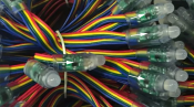
However, this year I thought I would get some 12mm Bullet Pixels to put into some props that didn’t have pigtails, to allow me to neatly customise the number of Pixels, as well as keeping down the cost.

However, unlike square pixels, I couldn’t see any arrow or anything that would show the direction the data would flow, so I’m unsure how to wire it up and hoping someone could assist.

When it didn’t work the first time, I then tried adding signal from the other end, but it still didn’t work. So, if I got it wrong the first time and connected it in reverse, would this have damaged the Pixels, and if so, is there any way to fix them (e.g. cutting off the first Pixel which may have been damaged)?

This is a link to Ray Wu’s store, to a similar string, but this one does appear to have a plug on one end, unlike mine.
https://www.aliexpress.com/store/pr...l?spm=2114.12010615.8148356.10.5d71cf77TIhblN
 

MD389

New elf
Joined
May 31, 2018
Messages
42
The PCB should have a small arrow on one side to indicate data in side. I've blown up the image from the store listing and added some arrows that look right.

** Edit ** Just noticed picture has 4 wire leads, are your 3 or 4 wires per pixel?

Found with the last batch I got that it could be hard to see the PCB as the epoxy stuff was cloudy or had trapped air bubbles so had to check a later pixel and work backwards.
 

Attachments

  • pixel arrows.PNG
    pixel arrows.PNG
    2.2 MB · Views: 41

djgra79

My name is Graham & I love flashing lights!
Global moderator
Generous elf
Joined
Dec 27, 2011
Messages
2,161
Location
Cranbourne West
Usually you can apply some drops of water (or spit!) to the node and it clears up the frosted look, allowing you to see the PCB inside much clearer
 

fasteddy

I have C.L.A.P
Global moderator
Joined
Apr 26, 2010
Messages
6,648
Location
Albion Park NSW
Generally the outer wires will be positive and ground and the inner wires will be data and clock (if 4 wire). So what is important is that you work out the positive side because if you put positive on the negative side then you may have some dead pixels. if you mix the data wires with the ground then normally no harm is done
You can confirm the ground and positive by using a multimeter as you should see a circuit from the front of the string to the end of the string as the positive and ground wires are connected in parrallel where as the data will either show a very high resistance or no circuit at all between the end front and end of a string as that is connected in series
 

abundy

Full time elf
Joined
Dec 27, 2011
Messages
107
Location
Doncaster East
On my bullet nodes which are 2811's, the output side of the pixel is the side that has the IC (8pin) on it.
The other side of the board there is a 3 pin transistor (i think) which is the input side.
with led pointing away from you the inputs are
12v Di Gnd
R G Bl
 

Stkilda123

Apprentice elf
Joined
Mar 19, 2019
Messages
68
Location
Australia
I'm also trying to figure out which end is the data in and out, as mine dose not have an arrow (i swear I've spat and cleaned but no arrow).
I do have "12v Di Gnd" displayed on 1 side of each pixel and a black chip on other side.
At one end of the line the wires enter to the "12v Di Gnd" displayed side, i think this would be the data in end,
And at the other end, the wires finish on the non written side (chip side), i'm thinking that will be the data out end,
Can someone let me know if they think this is right?
Thanks
 

Giles1

Giles
Generous elf
Joined
Dec 19, 2016
Messages
91
Location
Brisbane
upload_2019-6-21_20-51-52.jpg upload_2019-6-21_20-51-53.jpg upload_2019-6-21_20-51-53.png
On my bullet nodes which are 2811's, the output side of the pixel is the side that has the IC (8pin) on it.
The other side of the board there is a 3 pin transistor (i think) which is the input side.
with led pointing away from you the inputs are
12v Di Gnd
R G Bl

Yes, I wasn’t able to see an arrow anywhere on the Pixel either.

I agree with your wire colour/functions as well. So just to make sure, the wires coming out of the side of the Pixel with the black rectangle on it (which should be the 8-Pin IC), should be the outgoing wires (the ones going to the next Pixel).

As I don’t believe I’ve crossed the +/- wires, I shouldn’t have damaged anything (feigners crossed). So I’ll give it another go tomorrow.
 
Top