Navigation
Install the app
How to install the app on iOS
Follow along with the video below to see how to install our site as a web app on your home screen.
Note: This feature may not be available in some browsers.
More options

You are using an out of date browser. It may not display this or other websites correctly.
You should upgrade or use an alternative browser.
You should upgrade or use an alternative browser.
Sending data to pixels over 8 bundled (data) wires
- Thread starter Nova
- Start date
TerryK
Retired Elf
My thoughts: I think @Grozzy is on the correct track. Most if not all ESP devices (I do not use them) are 3.3 Volt and if you are feeding it 5 Volt it either has an on-board 5 to 3.3 volt regulator or you are over-voltage stressing the device. As you have yet to indicate what type of ESP you have, I am more likely to assume your ESP has a 5 to 3.3 Volt regulator on-board. In either case, the ESP outputs are running (or trying to run) 3.3 Volt data signals.I am supplying 5V power to my esp. Would that mean the data cable is only providing 3.3V?
So if I were to create my own differential controller using MAX485 boards or using pre-built boards, would that solve my issue?
Do I need to bring the data up to 5V from the esp before it reaches the differential transmitter?
As pixels want a 5 volt data signal, ESPs are seldom able to drive pixels much past a meter distance if that much at all. Other ACL members have already mentioned 3.3 to 5 volt level converters, RS-485 converters, and F-Amps. Any of these should strengthen the ESP data signals enough to give you the 5 to 10 meter distance.
To answer your question, the ESP's 3.3 volt data signal would not need bumped to 5 volt before it is feed to a differential converter (a RS-485 converter or similar) BUT the converter design must be such that it can properly handle a 3.3 volt data input signal. Pleaase note that I think using a differential converter for 5 to 10 meters is somewhat unnecessary. Another thought, the video shows the RJ-45 cable to be shielded but you have it plugged into a non-shielded keystone jack. Shielded RJ-45 jacks are available to carry the shield through. If the Ethernet cable is data only there is a fair chance that the 9th wire for ground will work reasonably well although I must admit it isn't anything I would suggest.
With that mentioned what I would suggest is as already mentioned, place 3.3 to 5 volt level shifters on the ESP outputs. Also obtain either a 9 or 10 conductor cable and 9/10 pin connectors and eliminate the Ethernet cable/connectors. 9/10 can be a bit hard to locate so I would I think run a pair of 5s.
Grozzy
Oh great, the idiot's back
- Joined
- Aug 16, 2018
- Messages
- 108
I personally think the rs485 path is a bit of an overkill unless you want to go 30m away. For what you are trying to achieve with the prop being a few metres away then just a buffer/shifter will do and as Terry said will likely need anyway. 
Ignore the P8 input labelling as that is for a beagle bone board but could be fed from your individual esps.

That was my first year megatree controller with 2 ESP-01 and it worked no issues.
And this was my indivual ones that used a 74ls125 chip.

On a side note ensure you use a dedicated wifi router with only show traffic. Once you get past 6 or so esps lag become a real issue.
Ignore the P8 input labelling as that is for a beagle bone board but could be fed from your individual esps.
That was my first year megatree controller with 2 ESP-01 and it worked no issues.
And this was my indivual ones that used a 74ls125 chip.
On a side note ensure you use a dedicated wifi router with only show traffic. Once you get past 6 or so esps lag become a real issue.
- Thread starter
- #19
My esps are standard ESP32s. (https://www.aliexpress.com/item/1005001636295529.html?spm=a2g0o.order_list.0.0.4f121802kIg6Sz - variant 38Pin)As you have yet to indicate what type of ESP you have
I just tested the voltage output of the esp. It supplied between 4.97 - 5.07V close to the esp, and ~4V after travelling over the ethernet line before it reached the first light. (Total distance tested is around 3-4m from esp to first light).In either case, the ESP outputs are running (or trying to run) 3.3 Volt data signals.
I originally planned to run regular UTP (hence the plastic keystone). So I jerry-rigged the ground wire for shielding.RJ-45 cable to be shielded but you have it plugged into a non-shielded keystone jack.
I know old serial cables use 9 pins. I was planning on using UTP with RJ45 because it is so common and easily sourced.9 or 10 conductor cable and 9/10 pin connectors and eliminate the Ethernet cable/connectors. 9/10 can be a bit hard to locate so I would I think run a pair of 5
How far can the data signal run if I use one of those? Would I still have issues with interference?just a buffer/shifter will do and as Terry said
On another note, is my problem interference or am I just under-supplying the required voltage?
Last edited:
- Thread starter
- #20
I have this. I am experiencing wifi issues so I am investigating ways to use Ethernet and attach a W5500 to my esps.dedicated wifi router with only show traffic
The video you showed... I am not thinking it is interference. Is it easy to try running them a lot closer together? Do you have a scope to watch the data signal received?
If no simple experiments can be done, I guess speculating is possible.
Keith did a very good video or two about this.
View: https://m.youtube.com/watch?v=9ttEAyiyTAI
It explains all the issues I have seen with mine.
The WS2811 chips and similar have circuits that are surprisingly tolerant, for locking onto the signal and establishing the pattern of reset, 0, or 1. They show remarkable behavior in adapting to the input, adjusting over the course of several seconds (caught me by surprise the first time I watched them look dead, then gradually flicker to life, reading too many 0s at first but eventually coming to proper color). What they are bad at is handling significant, rapid voltage fluctuations on the ground, data, and (maybe) power lines. This usually results in loss of data signal (leaving prior pattern lit, which is often bright or white), or reading all 0s (when the ground gets pulled up, and the pulse energy shrinks, usually triggered by sudden white, and then because it is all 0s it goes all black and the ground voltage returns, so it reads properly, goes all white, and the cycle repeats, leading to a flicker. Less common, but possible, is for them to adapt, then have the ground voltage drop a bit, and read all 1s, locking on white (usually followed by pulling ground up, and not reading data at all from that point on).
You aren't seeing a few 1s or 0s swapped, so it isn't high frequency noise. I see spots where they go white when they shouldn't, which indicates an abrupt increase in the delta between data high and ground. So thinking overall voltage fluctuation is to be blamed.
There are a few experiments you can do, but depends on the equipment you have.
- Thread starter
- #22
Not really. My aim was to try and keep most of the electronics undercover away from sprinklers and other water sources.Is it easy to try running them a lot closer together?
If interference is not my issue, is there a way to force the data down the line to the other end without having a possible voltage drop along the way?
I will definitely watch the video that you provided. Thank you for sending it in.
Is there a device or such that could easily fix this? Any solution is a good solution!increase in the delta between data high and ground
darylc
404 darylc not found
- Joined
- Dec 8, 2012
- Messages
- 1,290
Please add the buffer chips that other people referred to, this is the proper solution. You are trying to send a 3.3v data signal to a device expecting a 5v data signal, and putting them a long way away from each other (which causes more voltage drop) then wondering why they won't work.Not really. My aim was to try and keep most of the electronics undercover away from sprinklers and other water sources.
If interference is not my issue, is there a way to force the data down the line to the other end without having a possible voltage drop along the way?
With a decent controller (eg correct voltage on the data output and resistance on the line as per the ws2811 reference diagrams), you can run pixel data over cat5 for reasonable distances easily. I've done 10-20m in the past.
Hooking up ESP directly to pixels breaks all the design intentions for the WS2811, whilst you'll get away with it on the bench, you aren't going to get away with it as you've found in the field.
Last edited:
- Thread starter
- #24
What is my best option?Please add the buffer chips that other people referred to
Hanson Electronics has a null pixel extender.
Falcon has f-amps.
Is there a difference? Do they act like pixels and just require to be skipped?
And where should they be added? At the esp or near the first pixel?
Last edited:
Grozzy
Oh great, the idiot's back
- Joined
- Aug 16, 2018
- Messages
- 108
Whilst I'm the first person to push boundaries, and be unconventional I also have a strong background in Electronics and respect that certain things need to be done properly otherwise they come back to bite you. I strongly suggest you ditch the cat5 path and just get yourself xconnect/RayWu pigtails and use extension cords. Paul from LightemUp is in Perth and can supply what you need. Get rid of all the jst connectors or at least solder wires onto the connectors and then seal them. By the time you muck around with the esp and add buffers you are better spending $200 on a proper controller HE123, Falcon. If you do want to persist pm me your address and I'll send you one of my 8 port prototypes.

These both do the same thing.What is my best option?
Hanson Electronics has a null pixel extender.
Falcon has f-amps.
Is there a difference? Do they act like pixels and just require to be skipped?
And where should they be added? At the esp or near the first pixel?
No difference between them, except how they are packaged.
They do not act like pixels, they will just re-buffer the data line and give a nice low drive impedance to allow a long cable run. They are invisible to the WS2811 signal they are passing.
They should be added at the source, before the long line.
In your case they will provide two benefits - 1. boosting the signal to the 5V that should be used for a data line, and 2. Providing a nice strong source of power to give it a bit of extra throw.
orlandoal
Angry Elf!
I am by no means an expert on this, but the closer to the mega tree the controller, the better the signal.
Also looking at the way you have the wires connected I would have thought that might well introduce data loss. I appreciate that all you are doing is testing currently.
Are you in a position to build yourself a box and as suggested run Ray Wu or similar tails and connect in that way. I have a requirement for several props on the front of the house, I built a couple of boxes for my ESP controllers, I included in the box a network switch to connect the signals and also an ethernet out port to pass on to the next box if required. The only difference between us here is that I am running 12v pixels.
If I have totally missed the point or got your issues wrong, apologies.
A few pics to show what I mean
Attachments
- Thread starter
- #29
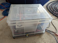
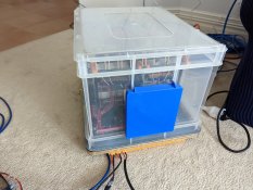
Still very much in the testing phase. What you see in the video is the main plan as far. I am actually creating this show with someone else who is very opposed to having electrical components such as ESPs and power supplies in the weather. So a bit of give and take is required. The power box which is shown in the video is covered with a large plastic lid with fans to supply fresh air into the box.I am by no means an expert on this, but the closer to the mega tree the controller, the better the signal.
Also looking at the way you have the wires connected I would have thought that might well introduce data loss. I appreciate that all you are doing is testing currently.
Are you in a position to build yourself a box and as suggested run Ray Wu or similar tails and connect in that way. I have a requirement for several props on the front of the house, I built a couple of boxes for my ESP controllers, I included in the box a network switch to connect the signals and also an ethernet out port to pass on to the next box if required. The only difference between us here is that I am running 12v pixels.
If I have totally missed the point or got your issues wrong, apologies.
A few pics to show what I mean
Thank you for sending in the photos. I like to see different ideas and designs that provide the same reliable result.
I will send pictures when I have finished testing and have it set up in the final stages.
- Thread starter
- #30
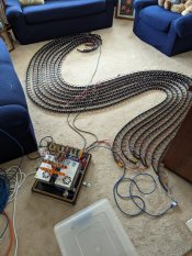
Turns out I found a solution faster than I originally thought!
For each data line, I added a Null Pixel at the beginning to improve the voltage drop.
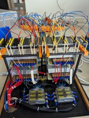
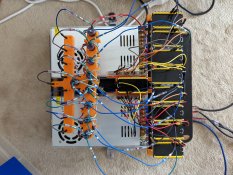
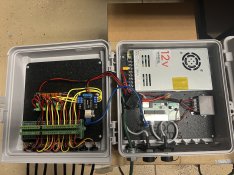
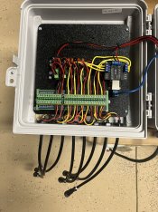
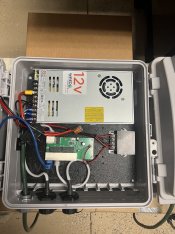
I have added a few photos of the power box that I created which will power and run the whole tree.
Thank you to everyone for all of your help!
 youtube.com
For each data line, I added a Null Pixel at the beginning to improve the voltage drop.
I have added a few photos of the power box that I created which will power and run the whole tree.
Thank you to everyone for all of your help!
- YouTube
Enjoy the videos and music that you love, upload original content and share it all with friends, family and the world on YouTube.
youtube.com