2 new boards

AAH

I love blinky lights :)
Community project designer
Joined
Dec 27, 2010
Messages
4,188
Location
Eaglehawk
I have 2 new boards under development. These boards are designed specifically to attach to a Raspberry Pi and a Beagle Bone Black. They will be controlled via the Falcon Christmas FPP (Falcon Pi Player which is now called the Falcon Player). They can operate as a totally standalone player or could be used as E1.31 controlled boards like J1Sys or SanDevices boards are.
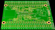
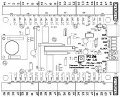
The Pi board will have 36 DC channels in 2 banks with 30A per bank. It will have a real time clock for the Pi and a power supply that can run the Pi so that no power adaptor is required. It will also have a 2801 pixel protocol output that is for cascading to my 2801DC boards but it could be used for 2801 pixels. At this stage the board is looking like being about 125mm x 100mm with the PI plugging onto the top of the "DC" board.
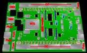
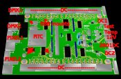
The Beagle Bone Black board is a bit further away and it will do a lot more. It will have either 18 or 36 DC channels, 2 DMX outputs that may be configured as DMX or pixelnet, a real time clock, the same 2801 cascade output as the Pi board and 2 or 4 pixel outputs. Depending on the number of DC outputs I go with the board will be only slightly larger than 125 x 100mm and the BBB will plug onto the top of it so that the leds and everything else are visible.

The Pi board I'm hoping to have about the end of March with the Beagle board a week or 2 later.
 

AAH

I love blinky lights :)
Community project designer
Joined
Dec 27, 2010
Messages
4,188
Location
Eaglehawk
My Beagle Bone Black turned up today so I can start work on that cape now :)
I'm waiting on my real time clock bits to come in so I can measure them so my Pi cape is currently in limbo until them.
The Pi cape is currently labelled with the bring title of PI36. Not much for originality.
 

Attachments

  • pi36.jpg
    pi36.jpg
    141.8 KB · Views: 36

djgra79

My name is Graham & I love flashing lights!
Global moderator
Generous elf
Joined
Dec 27, 2011
Messages
2,161
Location
Cranbourne West
I'm interested to hear/see more of the pi board - I think this would suit my needs this year.
 

AAH

I love blinky lights :)
Community project designer
Joined
Dec 27, 2010
Messages
4,188
Location
Eaglehawk
The PI36 gets sent off to have a few proto pcbs made today.
Basic specs will be
-36 DC channels rated at 30A per 18 channels. Individual channels rated at 5A.
-2801 output for carry over to my 2801DC15 or 2801DC 30 boards. Alternatively some 2801 pixels could be hooked up to this output.
-7-36V DC input. The maximum voltage is limited by the regulator. If 5V outputs are used there is a 5V input for powering the board.
-Test switch with a matching LED to turn on or off a test mode.
-Power leds for the 2 DC inputs and the 5V power.
-PI is powered by the onboard regulator.
-PI mounts above the board with "easy" access to the USB, Ethernet, SD, audio and video connectors.
-Mounts to suit the 2 standoff and 4 standoff varieties of the PI. Note these mounts may not suit some version 1 PI's as the footprint varied depending on manufacturer.
-Real time clock onboard for show scheduling.
 

Attachments

  • PI36-overlay.jpg
    PI36-overlay.jpg
    110.4 KB · Views: 40

AAH

I love blinky lights :)
Community project designer
Joined
Dec 27, 2010
Messages
4,188
Location
Eaglehawk
I got word today that my PI-36 cape pcb's will leave China on the 13th which is days later than I was hoping for :(

Whilst waiting I have started on the BBB cape. It looks like I will be able to squeeze everything onto a board about 6" x 5".

The planned specs are a bit up somewhat from the PI-36 due to the additional processing power and available outputs.
Basic specs will be
-36 DC channels rated at 30A per 18 channels. Individual channels rated at 5A.
-2801 output for carry over to my 2801DC15 or 2801DC 30 boards. Alternatively some 2801 pixels could be hooked up to this output.
-7-36V DC input. The maximum voltage is limited by the regulator. If only DC 5V outputs are used or if the DC outputs aren't used there is a 7-36V input for powering the boards. The cape and BBB have separate regulators.
-Test switch with a matching LED to turn on or off a test mode.
-Power leds for the 2 DC inputs and the 5V power.
-BBB is powered by the onboard regulator.
-BBB mounts above the board (on left above real time clock (RTC)) with "easy" access to the USB, Ethernet, SD, audio and video connectors.
-Mounts via the 4 BBB standoffs
-Real time clock onboard for show scheduling.
-2 pixel outputs that can be configured as 4 of 3 wire 2811, INK1003 etc, 2 of 4 wire 2801 etc or a single 4 wire and 2 3 wire pixels. 680 pixels per output (max 2720 if 4 3 wire are used) with 1 fuse per pixel connector.
-2 isolated RS485 outputs that can be configured as DMX or pixelnet and possibly Renard

As yet the cape has no name as I can't think of 1 that suits it's diversity.
 

Attachments

  • BBB-cape.jpg
    BBB-cape.jpg
    67.5 KB · Views: 23

AAH

I love blinky lights :)
Community project designer
Joined
Dec 27, 2010
Messages
4,188
Location
Eaglehawk
Without knowing the exact details of the flood I would have to say that yes they would. It will do any of the dumb RGB stuff that has a common +ve (up to a max of 36V).

arw01 said:
Alan, when you say DC, would these also run FLOODS, e.g. the dumb type floods with +RGB and the common?
 

AAH

I love blinky lights :)
Community project designer
Joined
Dec 27, 2010
Messages
4,188
Location
Eaglehawk
My PI36 cape pcb's didn't turn up on Thursday as they were scheduled to or today as I hoped they would. I really can't see how it can take more than 4 days to travel the 150km from Melbourne to Bendigo :mad:
While waiting I started the routing of what is now unofficially called the BBB36+. It looks like it is going to be about 6" x 5" with the Beagle Bone Black (BBB) mounting on top of the cape with everything nice and easy to get to. The DC outputs will be top and bottom of the cape with all the power, pixel, dmx etc connectors on the left and right. The BBB's own connectors etc as well as it's switches and LED's should all be visible and easily accessible. If all goes well it should be up and running about the same time as MINI season hits Aus :)
Since chatting with AussiePhil in chat I added a few extra features to the board that for the short term are a secret between Phil and I. These will add even more functionality and flexibility to the board.
 

Attachments

  • BBB36+.jpg
    BBB36+.jpg
    124 KB · Views: 28

AAH

I love blinky lights :)
Community project designer
Joined
Dec 27, 2010
Messages
4,188
Location
Eaglehawk
PCBs turned up this morning so now it's time to start loading a couple of boards to test.
They're a tiny looking board. Only 3/4 of the size of my DMX36 boards with all the extra goodness that the PI has to offer.
 

AAH

I love blinky lights :)
Community project designer
Joined
Dec 27, 2010
Messages
4,188
Location
Eaglehawk
Ben was after a copy of the PI36 manual prior to the Sydney mini so he could have a read. The manual is nowhere near complete yet as there are no photos of the board, the board with the PI mounted on top or screenshots of the setup procedure in FPP. It's a manual at least though :D

It seems that the pdf conversion process makes a mess of the front cover picture but you get the idea.
 

Attachments

  • PI36 preliminary manual.pdf
    929.3 KB · Views: 20
Top