dougd
Full time elf
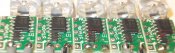
What is the amperage on 1 of those strobes, trying to figure out how many I can put on 1 string and what gauge wire to use.
Follow along with the video below to see how to install our site as a web app on your home screen.
Note: This feature may not be available in some browsers.

AAH said:I haven't actually built up a string of these so it makes it hard for me to give you an actual current which really needs to be averaged across a dozen or more strobes but what I can say is that nzlongfellow posted a video and a note saying that he had 100 of them running off 90m of 2mm cable. At a guess I'd say you could probably say that the strobes have an average current of 30mA (350mA @ 9% duty cycle) and they will run down to about 3.6 to 3.7V at the end of the string and still work.
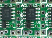
AAH said:My Chinese pcb loaders screwed me over and there appears to be some random loading of some of the PIC IC's. Below is a picture that shows 2 PICs that are inserted wrong. The dot that marks pin 1 is closest to the NUD LED driver rather than being closest to the edge of the pcb. If you have any of these boards don't power them up. The PIC can be swapped over but powering up the board will destroy the PIC. Out of the 144 strobes of mine I found 5 that were around the wrong way. Other people have found none.
Boomer said:Alan I only have one PIC on backwards by the looks of it. That's 1 out of 96, not bad IMO.
Thanks for the tip, Cheers
")
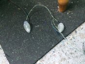
drlucas said:I ended up driving them from a single channel on a mr16 I got from DLA. Video isn't the best as I took from inside the house.