Another power injection question

No1Daemon

New elf
Joined
Sep 20, 2021
Messages
19
Hi guys.
I know these get asked a lot but I am having difficulty and could use some advice.

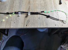
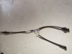
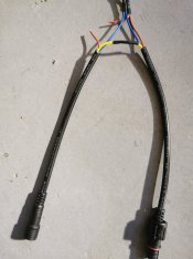
I didn't have any power injection tees on hand so for testing purposes I thought I would make one.

I am using 5v seed pixels and I used 2 female and one male connector to diy a tee.

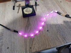
My led strings both light up well when directly connected together and Function as expected.

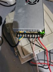
I carried the yellow data wire and v-(blue) through as I am using 2 different power supplies and I read it was best not to connect the v+(brown) so I cut it at the power injection point.
Does that look correct? Because it doesn't behave as it should.
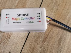
From the second controller only the brown and blue wires are connected.

Have double checked all the wiring but it just isn't working the same as when connected directly.

Have I failed to understand something?
 

Attachments

  • IMG_20240418_094352.jpg
    IMG_20240418_094352.jpg
    695.5 KB · Views: 17
  • IMG_20240418_094339.jpg
    IMG_20240418_094339.jpg
    457.8 KB · Views: 17

thewanderingpine

Full time elf
Joined
Mar 13, 2021
Messages
318
What do the pixels do after the T?

and just in-case — what is your second controller? Does it have Efuses?
 

No1Daemon

New elf
Joined
Sep 20, 2021
Messages
19
Hi

Sorry I edited that. There is no second controller, that should have said "second power supply"
The tee is connected after the 1st 50 pixels to inject new 5v power for the next 50
 

MikeKrebs

Full time elf
Joined
Dec 8, 2014
Messages
168
What is the exact symptom? It doesn't behave isn't very descriptive.

Did you set the controller for more than 50 pixels?
 

No1Daemon

New elf
Joined
Sep 20, 2021
Messages
19
Hi. Sorry you are correct. It isn't very descriptive. Looks like it shorted somehow. I have had to remive some leds and have made a small testing string for now.

I am using a small tester that generates patterns on the test bench instead of unpacking the controller.

Can you confirm that what I have done should work?

Leave the data line intact. Break the v+ so both psu are not connected and leave the v- connected as it's part of the data circuit. So second string of leds is the only one fed v+ from the second power supply

Is there anything obvious in the photos I supplied that looks wrong?

Perhaps a connector was wired incorrectly?
 

thewanderingpine

Full time elf
Joined
Mar 13, 2021
Messages
318
It sounds right to me. I assume you’ve checked the things like (are both PSU’s he same voltage).
Is the new testing string working? Or still failing?
 

No1Daemon

New elf
Joined
Sep 20, 2021
Messages
19
Just in the process of checking what I can still.
The PSU are both the same voltage. The new test strings work fine. But I haven't yet tested and made another tee.
I'll check the ends before connecting anything better to try and ensure it won't happen again.
 

Mark_M

Annoying Elf
Joined
Dec 30, 2018
Messages
924
Location
Christmas Light world
What power supply are you using are are you seed pixels 3 or 4 wires?
I'm wondering if there could be fault from a bad power supply or signal interference.
 

No1Daemon

New elf
Joined
Sep 20, 2021
Messages
19
Hi Mark. Thanks for the reply.
They are 3 wire seed pixels.
I have had similar results with my regulated DC power supply and 2 different power supplies so far.
 

Mark_M

Annoying Elf
Joined
Dec 30, 2018
Messages
924
Location
Christmas Light world
Hi Mark. Thanks for the reply.
They are 3 wire seed pixels.
I have had similar results with my regulated DC power supply and 2 different power supplies so far.
Do you have photos of the complete system connected to the pixels?
A picture paints a thousand words in spotting the issue :).

Some ideas of frustration from my own pixel journey;
I used Bunnings outdoor garden lighting cable. It was 0.75m^2 copper but it has such a large voltage drop across it that my pixels wouldn't reach full brightness. Compared to not using that cable.
Another example I had was a 12v Meanwell power supply which was faulty. It measured 12v DC to my meter but it had such bad ripple that my pixels red colour was dying on it.
 

No1Daemon

New elf
Joined
Sep 20, 2021
Messages
19
Each time I have wired it and failed I've started again.

I will wire it up again and take some photos.
Appreciate the advice
 

No1Daemon

New elf
Joined
Sep 20, 2021
Messages
19
I have attached a few photos.
Photo 1 is the controller
Photo 2 is the power supply. It's generic and not the greatest wire but it's working. With these 2 a string of over 100 seed pixels will light up fine.
Photo 3 shows my first test string wired and working with in and out connectors
Photo 4 shows the 2nd test string with in connector and working fine. Ignore the colors. It's a random pattern not a lack of power. Also works fine on a set color with no fading.
The difficulty then starts when I attempt to power inject.
I have tried both from one power supply where I have left all 3 wires connected through and teed into it before the next led at v+ and v-
I am reading 5.1 volts at the power injection connection and the polarity is correct.
This resulted in some dead pixels on string 2
I have also tried leaving the v- and data connected right through and cut the v+ from the first power suppy before the first led and connected my power injection connector to the v+ input to the next led and also connected the v before the first led to tie the neutral of both power supplies together. And this all resulted in killed pixels.

Not sure what I am missing.
 

Attachments

  • IMG_20240423_162724.jpg
    IMG_20240423_162724.jpg
    972.2 KB · Views: 17
  • IMG_20240423_162733.jpg
    IMG_20240423_162733.jpg
    382.5 KB · Views: 15
  • IMG_20240423_161232.jpg
    IMG_20240423_161232.jpg
    1.2 MB · Views: 14
  • IMG_20240423_162711.jpg
    IMG_20240423_162711.jpg
    1.1 MB · Views: 14
Top