Arduino et Xlight

Youpcoco

New elf
Joined
Sep 23, 2023
Messages
2
Bonjour, j'ai actuellement une configuration qui fonctionne avec un logiciel arduino mega et vixen. Ceci est utilisé uniquement pour allumer ou éteindre les lumières. Je voudrais passer cette configuration à Xlight au lieu de Vixen. Pouvez-vous s'il vous plaît m'aider car je n'arrive pas à comprendre. Merci.


Translation:
Hello, I currently have a setup that works with arduino mega and vixen software. This is only used to turn lights on or off. I would like to switch this configuration to Xlight instead of Vixen. Can you please help me as I can't figure it out. THANKS.
 

Skymaster

Crazy elf
Global moderator
Generous elf
Joined
Dec 19, 2021
Messages
1,069
Location
Western Sydney
How is vixen currently outputting data to the Arduino?
Based on your current connectivity, that setup could be replicated into xLights, and after that the definitions of three lights on your layout could be mapped on for sequencing.
 

MikeKrebs

Full time elf
Joined
Dec 8, 2014
Messages
168
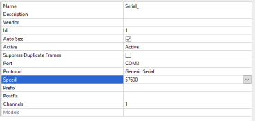
You didn't give much info about what your configuration is or what the actual problem is. Likely you are using generic serial so you want to set up a generic serial USB controller. Select Generic Serial, save it, click back into the controller and you set the speed to whatever is in your sketch. Set the com port you are using. You probably have a Prefix so put that in there. Then set the number of channels and save it again.

1695439353990.png
 

CargoLights

Apprentice elf
Generous elf
Joined
Sep 16, 2020
Messages
79
Location
Grantsville, Utah, United States
I had a setup that sounds very similar to yours before I switched to pixels. When I first switched to xLights from Vixen, I connected the Arduino to a Rasperry Pi and configured it as a serial output. That ran the relays fine, but I ended up abandoning it for a full pixel display that first year, so I never did more than test it. If you want to use a Windows computer running xLights directly connected to the Arduino, you'll need to click Add USB in xLights and configure it. You'll likely want the Protocol to be Generic Serial (depending on the code you are running on your Arduino) and you'll need to set the speed to the bitrate your code expects. You'll also need to figure out what COM port your arduino is on and configure that.
 

Youpcoco

New elf
Joined
Sep 23, 2023
Messages
2
Bonjour à vous.
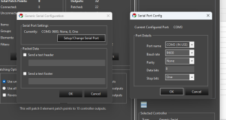
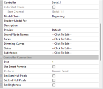
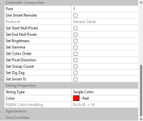
Merci pour vos réponses. Malheureusement, je pense avoir déjà répondu à vos demandes. Voici la configuration saisie concernant le contrôleur et aussi la configuration de l’élément à activer/désactiver. Xlight communique avec l’arduino mais ne réagit que sur le même relais et non sur le bon.
Je joins également la configuration de Vixens qui fonctionne et le code entré pour arduino

Translate:
Hello to you.
Thank you for your answers. Unfortunately, I think I have already responded to your requests. Here is the configuration entered concerning the controller and also the configuration of the element to activate/deactivate. Xlight communicates with the arduino but only reacts on the same relay and not on the correct one.
I also attach the Vixens setup that works and the code entered for arduino

#define MEGA_VIXEN
#define UNO_VIXEN

#ifdef MEGA_VIXEN
#define MAX_CHANNELS 32
int channels[MAX_CHANNELS] = {2, 3, 4, 5, 6, 7, 8, 9, 10, 11, 12, 13, 14, 15, 16, 17, 18, 19, 20, 21, 22, 23 , 24, 25, 26, 27, 28, 29, 30, 31, 32, 33};
#endif

#ifdef UNO_VIXEN
#define MAX_CHANNELS 8
int channels[MAX_CHANNELS] = {2, 3, 4, 5, 6, 7, 8, 9};
#endif

#define POWER_UP_STATE HIGH //0 = Lumières éteintes à la mise sous tension, 255 = lumières allumées à la mise sous tension
#define INACTIVITY_STATE LOW //0 = Lumières éteintes lorsqu’elles sont inactives, 255 = Lumières allumées lorsqu’elles sont inactives

#define INACTIVITY_TIMEOUT_MILLISECONDS (5UL * 1000UL) // 5 = 5 secondes, 1000 = 1000 millisecondes en une seconde

int incomingByte[MAX_CHANNELS];

inactivité longue non signéeTimer;

void setup()
{
int i;

Serial.begin(9600); configurer Serial à 9600 bps

pour (i = 0; i < MAX_CHANNELS; i++)
{
pinMode(canaux, SORTIE);
digitalWrite(canaux, POWER_UP_STATE);
}

inactivityTimer = millis();
}

void loop()
{
int i;

if (Serial.available() >= MAX_CHANNELS)
{
for (i = 0; i < MAX_CHANNELS; i++) incomingByte = Serial.read();
inactivityTimer = millis();
}

if ( (millis() - inactivityTimer) >= INACTIVITY_TIMEOUT_MILLISECONDS )
{
for ( i = 0; i < MAX_CHANNELS; i ++ ) incomingByte = INACTIVITY_STATE;
}

for (i = 0; i < MAX_CHANNELS; i ++ ) digitalWrite(channels, ~incomingByte);
}
 

Attachments

  • Capture d'écran 2023-09-22 165004.png
    Capture d'écran 2023-09-22 165004.png
    51.6 KB · Views: 10
  • Capture d'écran 2023-09-22 165042.png
    Capture d'écran 2023-09-22 165042.png
    24.8 KB · Views: 10
  • Capture d'écran 2023-09-23 082332.png
    Capture d'écran 2023-09-23 082332.png
    17.2 KB · Views: 8
  • Capture d'écran 2023-09-23 082343.png
    Capture d'écran 2023-09-23 082343.png
    18.3 KB · Views: 8

CargoLights

Apprentice elf
Generous elf
Joined
Sep 16, 2020
Messages
79
Location
Grantsville, Utah, United States
Are you running a sequence through xSchedule, or just trying to get output to lights to run it?

I may have to pull my old Arduino and relays off the shelf in the garage and see what it takes to make them run.

Your Arduino code looks functionally similar to what I found on an old drive (don't judge too harshly, I just slapped this together a decade ago):

int A = 2;
int B = 3;
int C = 4;
int D = 5;
int E = 6;
int F = 7;
int G = 8;
int H = 9;
int I = 10;
int J = 11;
int K = 12;
int L = 13;
int M = 14;
int N = 15;
int O = 16;
int P = 17;


int i = 0;
int incomingByte[16];

void setup()
{
Serial.begin(9600);

pinMode(A, OUTPUT);
pinMode(B, OUTPUT);
pinMode(C, OUTPUT);
pinMode(D, OUTPUT);
pinMode(E, OUTPUT);
pinMode(F, OUTPUT);
pinMode(G, OUTPUT);
pinMode(H, OUTPUT);
pinMode(I, OUTPUT);
pinMode(J, OUTPUT);
pinMode(K, OUTPUT);
pinMode(L, OUTPUT);
pinMode(M, OUTPUT);
pinMode(N, OUTPUT);
pinMode(O, OUTPUT);


}

void loop()
{
if (Serial.available() >= 16)
{
for (int i=0; i<15;i++)
{
incomingByte = Serial.read();
} // Arduino pins
digitalWrite(A, incomingByte[0]); // Pin 2
digitalWrite(B, incomingByte[1]); // Pin 3
digitalWrite(C, incomingByte[2]); // Pin 4
digitalWrite(D, incomingByte[3]); // Pin 5
digitalWrite(E, incomingByte[4]); // Pin 6
digitalWrite(F, incomingByte[5]); // Pin 7
digitalWrite(G, incomingByte[6]); // Pin 8
digitalWrite(H, incomingByte[7]); // Pin 9
digitalWrite(I, incomingByte[8]); // Pin 10
digitalWrite(J, incomingByte[9]); // Pin 11
digitalWrite(K, incomingByte[10]); // Pin 12
digitalWrite(L, incomingByte[11]); // Pin 13
digitalWrite(M, incomingByte[12]); // Pin 14
digitalWrite(N, incomingByte[13]); // Pin 15
digitalWrite(O, incomingByte[14]); // Pin 16
digitalWrite(O, incomingByte[15]); // Pin 17

}
}
 
Top