Controller Wiring - Using Power Bus line

Johnnyboy

Full time elf
Joined
Jan 2, 2023
Messages
155
Location
Perth
Hi All,

Looking at different options for wiring a large matrix, and at the same time trying to keep the weight down as much as possible. I am planning on having the garage door operational so the weight is quite important.

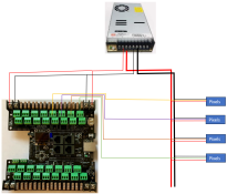
What i am looking at doing is running a power bus using larger gauge wire and then tapping into it at regular intervals by soldering in pigtails. It is looking like 16-20 channels of the below setup. I will be using a two large power supplies to run the controller. (i understand that data lines from each side of the controller will only be connected to the same PS etc)

Anyway, is there any issues with this layout? I've just received the controller so will be testing it out, but wanted to run it past the brains trust.

I was planning on using a 8core cable with one core to each set of pixels. Its looking like the maximum length from controller to pixels will be about 6-7m. I've used extension cables of that length before with good results. Running extension cables for each output will get heavy so hopefully this will work.
1712910773927.png


Thanks all
 

Skymaster

Crazy elf
Global moderator
Generous elf
Joined
Dec 19, 2021
Messages
1,064
Location
Western Sydney
Bring data and ground together from the controller to the pixels. (So two grounds, one big from the PSU, and one little from the controller)
Don't rely on the implicit ground only via the PSU.
The reason being is if you get any voltage rise on the negative due to current draw, your pixels will have data corruption issues.

Also, you only need to power the Kulp on one of the two input terminals. (the right in your image i believe). This is the one that feeds the electronics on the board. The other is only used for pixel power to the output connectors.
 

Hoodlum

New elf
Joined
Dec 7, 2020
Messages
28
You should be right going down that path - if you are 12v - you wont need too much power injection but depens on your density blah blah.
it's pretty much how i wired my matrix last year and will again this year.
my data lengths were only 4m from controller though
Matrix (3m x 2m) was just hanging in front of garage door so GD was not encumbered (im assuming you want to attach it to your garage door)
last year i used 3 data ports of 800 pixels,
i had data lines and power injection from bottom (bc 5v seed pixels) think i got away with 5 injection points over the 800 pixels (so 15 total across the matrix)
1 power supply of 12v 350w - had 3 x 12v to 5v bucks
ran it at 40% brightness
so yeah i had a data ground and a power ground - the grounds came together at the inection points.
so even as messay as that it worked well - anything better than that and you'll have youself some smooth sailing matrix magic!
this year will likely be 16 ports of 640 pixels (5v) and a HoHoHo tonne of power injection
 

Johnnyboy

Full time elf
Joined
Jan 2, 2023
Messages
155
Location
Perth
Bring data and ground together from the controller to the pixels. (So two grounds, one big from the PSU, and one little from the controller)
Don't rely on the implicit ground only via the PSU.
The reason being is if you get any voltage rise on the negative due to current draw, your pixels will have data corruption issues.

Also, you only need to power the Kulp on one of the two input terminals. (the right in your image i believe). This is the one that feeds the electronics on the board. The other is only used for pixel power to the output connectors.
I can't say i really understand the comment about the voltage rise on the negative, but more than willing to implement it to make sure it works.

You mention a second ground. Are you meaning a ground from each pixel output, or just another ground cable that is connected direct from the controller?

Where abouts would you connect it on the controller?
 

Skymaster

Crazy elf
Global moderator
Generous elf
Joined
Dec 19, 2021
Messages
1,064
Location
Western Sydney
I can't say i really understand the comment about the voltage rise on the negative, but more than willing to implement it to make sure it works.

Voltage "drop" is a differential across a piece of wire, due to its resistance.
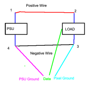
For maths - lets say we have a 10V input, with 1m of wire, and 8V reaches the far end as per the far diagram
1713091101982.png

The load on the power supply can be (roughly) modeled by three resistors -
1. Postive Wire
2. Load
3. Negative Wire

Assuming the wires are exactly the same length and diameter (ie same resistance), this means that each is dropping 1V.

Voltage is potential difference - it must be measured between two points. Typically we reference our measurements to ground- but; what is ground?

Lets look at the measurements in the above hypothetical circuit
  • Between Points 1 & 4, you'd measure 10V.
  • Between points 2 & 3, you'd measure 8V.
  • Between points 1 & 2, and also 3 & 4, you'd measure 1V.

If you were to measure each point in relation to PSU ground (point 4), you'd get:
  • 1 = 10V
  • 2 = 9V
  • 3 = 1V
  • 4 = 0V
So - we can see that the pixel ground is actually sitting 1V higher than the PSU ground, due to the voltage "rise" on the negative cable. It's the same as the voltage "drop" on the positive cable

Now, the issue comes with the data. The data is such a low current, that it does not cause any discernible voltage drop across the wire. This is a good thing.
But, lets say we have a 5V data signal, referenced to PSU ground - what does the pixel see?
5V at the data pin, and 1V at it's ground = so 4V. Not bad, the pixel can still interpret the data.

Now, we push the pixels harder over a longer lead. The pixels are now seeing 5V instead of 10V. This means that we are now measuring
  • 1 = 10V
  • 2 = 7.5V
  • 3 = 2.5V
  • 4 = 0V
The same issue occurs again with the pixel data - 5V minus 2.5V = 2.5V data signal!! Well outside the realm of valid data, so we get corruption. This is where F-Amps help. They re-reference the data, so that it's 5V in relation to that 2.5V (so in essence at 7.5V to the PSU) and the pixel sees the right 1's and 0's.

You mention a second ground. Are you meaning a ground from each pixel output, or just another ground cable that is connected direct from the controller?

Where abouts would you connect it on the controller?

By tying a second ground - as shown in cyan; this would provide a proper zero reference. The easiest woudl be to would bring the data and ground out from the pixel output port. One for each data run over a two core wire.
 

Johnnyboy

Full time elf
Joined
Jan 2, 2023
Messages
155
Location
Perth
Thanks for the detailed description Skymaster. I've read over your response a number of times and i think i understand it, but still quite complected for me.

By tying a second ground - as shown in cyan; this would provide a proper zero reference. The easiest woudl be to would bring the data and ground out from the pixel output port. One for each data run over a two core wire.
What size wiring would you recommend in this situation for both data and ground?

Thanks
 

Johnnyboy

Full time elf
Joined
Jan 2, 2023
Messages
155
Location
Perth
The current is so tiny that anything would do; there's no specific sizing needed. Use whatever you have available.
Would using Network cable work?
Was thinking 1 pair for each output - 1 data & 1 ground. Would get me 4 outputs in one cable?
 
Top