DMX tester

Another wish for the list.


2801 testing function. Have a second outlet for connection to a pixel string and have a test pattern for the first six pixels of RGB cycling to confirm the pixels are ok. Limiting to driven pixels to six or even three would keep power consumption down.


Maybe other pixel types could be a menu selection.
 
David_AVD said:
So, you guys are already heading down the path of making your own DMX tester?
I have had the Elektor unit for a couple of years.
The Henne and Elektor units are completely different beast. If I wont to a DMX multimeter that will allow me to Tx DMX in the field or make sure the value I am receiving for as particular channel then the Elektor is my first choice.
If I want to measure the MAB and other timing elements, see the relative level of a number channels then Hennes a good option.

Why repeat this information? Because if you are going to design YADA decide on what you want to use it for, pick your feature set and go for it.

BTW,
this year I am trying out a new tool. Remote Desktop on my Moto Xoom connected to the show computer. I had to add another Wireless AP to cover the garden. But I can do everything at the actual controller.
 
wjohn said:
Another wish for the list.

2801 testing function.

Maybe the pixel test part would supply data / clock signal only and use an adapter lead to inject power via an external source?
 
David_AVD said:
wjohn said:
Another wish for the list.

2801 testing function.

Maybe the pixel test part would supply data / clock signal only and use an adapter lead to inject power via an external source?


that would be fine, it would be easy to knock up a Y cable with Power coming in on one leg, and SPI data on the other, and go to your PIXEL connector of choice. That would give the 5 V, 12 V ?V pixel users any option they need, while have the DMX-PIXEL tester able to bit bash out a suitable framed data source and timing for a range of pixels, independent of the power supply...
 
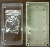
Here's the H0326 box from Altronics. It's actually a Ritec model RP1175C.

davidavd H0326 plastic enclosure from Altronics h0326.jpg

As you can see, it has plastic studs in the base. These are normally used to mount a metal plate, but I can make the PCB use the same mounting points. This means no drilling into the base and a no screw heads to scratch your table, etc.

Anyway, I'll add these small updates as I progress...
 
Was considering touch sensors for the switches as it would make the top water resistant, but they can be fiddly to use and are hard to press rapidly when adjusting numbers, etc.

So, maybe a PCB with these tactile switches and caps from Altronics?

S1135.gif
S1138.gif


Just throwing some more ideas around since there's not a huge rush on this project yet.
 
David

I might have some work that you can piggy back off as well from my days at DLA, I think both Firmware and basic PCB are done, though if you are incorporating SPI outputs then might not be a lot of use to you.

Phil
 
I've picked out a charger IC and boost converter IC so that the tester can be powered from little Li-Po battery and be charged by a common USB charger like you'd use on your iPod, etc.
 
Back
Top