ECG-P2 / ECG-D2 Quick Notes

j1sys

There are no rules, and those are the rules.
Community project designer
Joined
May 19, 2010
Messages
242
Location
Knoxville TN USA
Some shipments of ECG-P2 / ECG-D2 may be arriving in the next few days at people's doorsteps.

When they arrive they won't know what to do, how to configure, or anything.

Attached is a quick document on installing all the jumpers for the different common configurations. As stated in the document we removed ALL jumpers after testing and you will start with a blank slate which won't power up until you've made some decisions.

Also on the ECG-P2 the initial software release just treats it like a 2 string P12R. So only 1 universe per string. We are finishing up the multi universe per string option and will release very soon along with the newer pixel types everyone is screaming for.

Sorry for the timing, but I will be out of the office for the next 5 days to attend my nephew's wedding. I will have my laptop with me to answer any important questions that arise.

-Ed
 

Attachments

  • ECG-P2 ECG-D2 Quick Notes.pdf
    650.2 KB · Views: 2,133
oops. we just noticed the K1 power connector polarity is not labeled on the board (no room). it is labeled on the back panel if in cases. from the rear the left pin is negative, the right is positive. The P-POE and P-DMX connections use the industry standard pinouts.

-Ed
 
Got mine in! Now I just need my rgb strips to come in!
6c265c80-dc77-b835.jpg
 
With luck I should get mine next month or so. I think there are P2's around, but Ed has run out of P12R's, the other 1/2 of my order. Cant wait to play witht he P2 though, it looks like a great bit of gear
 
Received my P2 in the mail yesterday, and finally got a chance to try it out with LOR tonight. Works great! So far I've only tested with a few 6803 modules I had laying around, while I wait for my order of 2811's from Ray to arrive.

This is my first J1sys product, and I'm impressed. The UBL and HTTP configurations made setup a breeze. I like the Effects feature as well. Will save me a lot of time, not having to manually reconfigure the pixels for BGR within LOR. 8)

-Mark
 
Hi All,


Seems I may have found a design issue.


Here is a pic of my D2 with a burnt track at the bottom:
ecg-p2_burnt_track.jpg


After playing with the unit, I removed all the jumpers (so that I didn't end up injecting 12v when it is configured for 5v). Later I reconfigured the unit for 12v input.


I removed the jumper J4, it appears that has bridged the 12v+ with the case of the RJ45 sockets (which I assume is grounded), This caused the track to burn up (as seen at the bottom of the picture).


I have replaced the jumper J4 so that it is no longer bridging and the unit still seems to be working fine, however I am pretty sure P-DMX isn't going to work on this unit any more :)


Anyone else made this mistake yet?
 
Kaden said:
I removed the jumper J4, it appears that has bridged the 12v+ with the case of the RJ45 sockets (which I assume is grounded), This caused the track to burn up (as seen at the bottom of the picture).

Was it the springy metal part of the RJ45 shield the touched the jumper pin?
 
from the quick notes:
ECG-D2 – J4 – connects +V bus to P-DMX power pins for DMX port #2. If you want to feed the +V bus out to the P-DMX, or possibly feed the +V for the unit from another P-DMX device then install the jumper. The J4 jumper pins are dangerously close to the ‘fingers’ on the 2x RJ45 connector. For safety a jumper should be installed just on the pin near the edge of the board to isolate/insulate from a short to ground.

we do ship it with the safety jumper in place and show a photo of its proper placement.

sorry for your problem kaden. we may go to the trouble and recommend others remove the springy thing. these boards are just so small and tight that some minor mechanical 'tightness' issues didn't come to light until too late to find a way around them.

once you remove the spring or take care of keeping a jumper on it you could tack solder a piece of wire on the burnt out trace. just scrape back to bare copper and solder a piece of wire on.

-Ed
 
DSC_0539.JPG

DSC_0540.JPG

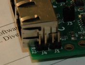
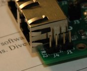
attached are two photos showing before and after on an ECO (engineering change order) that we will be applying to all ECG-D2 in stock before shipping. This same ECO should immediately be made on any ECG-D2 in the field.

just take a pair of diagonal cutters and cut the two fingers near J4 back from the pin. but do NOT cut the finger shorter than the edge of the board or you will have difficulty installing/removing the front panel.

-Ed
 
j1sys said:
from the quick notes:
I just read
We ship ALL units with NO jumpers installed. We didn’t want to make assumptions on power connections and uses and then have it fail (or worse burn up) when you connect to your wiring.
It's ironic that if you remove all jumpers from the board, it will burn up :p
Skim through this whole document, look at the pictures, look at the charts and then go back and read for detail if you need.
I decided not to read anymore of the doco then I needed to get it going (ie the table) :p
once you remove the spring or take care of keeping a jumper on it you could tack solder a piece of wire on the burnt out trace.
I didn't mention it in the post (but did in chat), that the board is still working and I don't use p-dmx so this doesn't affect me. I just wanted to make sure everyone knew so they don't do the same thing.
 
Back
Top