Meuretti
New elf
- Joined
- Apr 29, 2026
- Messages
- 1
Falcon F16v5 wiring schema for high-current 12V WS2815 installation — sanity check requested
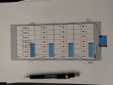
Building a 28-panel WS2815 LED screen (8×32 pixels per panel = 7,168 pixels total, 4 rows × 7 columns) for an art installation. Controller is Falcon F16v5, using 7 outputs (one per column). Each column = 4 panels in serial data chain via JST connectors. 7-day continuous run, exhibition hours 10:00–20:00, Swiss Art Awards Basel, 16–21 June 2026.
Power architecture:
- 4× Meanwell UHP-500 (12V, 500W each) — one PSU per row of 7 panels
- ~143A total at 100% white (verified: 0.24W/LED × 256 LEDs/panel × 28 panels = 1720W)
- ~36A per PSU, ~5.1A per panel
- Each PSU has 2× V+ and 2× V- terminals — splitting each row into two strings (4+3 panels) → ~20.5A and ~15.4A per terminal
- Power and data physically separated: V+ and GND go directly from each PSU to its panels, NOT through the Falcon
Per-row distribution (no daisy-chaining):
- Each PSU feeds two local busbars (V+ and V-)
- 7 individual dedicated wires from each busbar to each panel's V+ / GND
- All 4 V- busbars connected via a vertical GND backbone → common ground
Falcon F16v5 connections:
- External Power Input: +12V and GND from common ground (controller logic only)
- V1 and V2: GND only — no +12V (per-output E-fuse rated 5A, insufficient for ~36A/row)
- Output V-pins: unused
- Output G-pins: unused (GND runs externally via PSU)
- Output D-pins: connected to first pixel's DI and BI bridged together (full backup-data redundancy from pixel #1 onwards)
Inter-panel JST connectors carry only data (DI + BI), no V/GND.
Wire gauges (DC, runs <2m, real-world average 20–40%, 100% peaks rare and brief):
- PSU terminal → 4-panel string: 2.5 mm² (max 20.5A, real ~8A)
- PSU terminal → 3-panel string: 1.5–2.5 mm² (max 15.4A, real ~6A)
- Busbar → individual panel: 1.5 mm² (5.1A)
- PSU V- → common GND backbone: 2× 4 mm² in parallel (using both V- terminals)
- Inter-panel data (DI + BI): 0.5 mm²
- Falcon External Power: 0.75 mm²
- Falcon V1/V2 GND: 1.5 mm²
Connectors:
- Common GND backbone: copper busbar or high-current terminal block (>40A per terminal)
- Per-row local busbars (V+ / V-): WAGO 221-413 (32A / 4mm² rated) — one cluster per PSU
- Branch points to individual panels: WAGO 221-413
- BI+DI bridge at first pixel: WAGO 221-412 or solder
Specific concerns I'd like feedback on:
- Falcon V1/V2 GND-only configuration: Is V1/V2 with GND but no +12V valid on the F16v5, or does the output driver circuit require V1/V2 +12V to function even when output V-pins are unused?
- Common-ground topology: Per-row V- busbars chained via a vertical backbone (functioning as the common ground reference). Sufficient, or should I bring all 4 PSU V- to a single physical star point instead?
- BI+DI bridge at first pixel: Any concerns vs. the more common BI-to-GND configuration? My reasoning: full redundancy from pixel #1 onwards.
- Wire gauges — is 2.5 mm² sufficient for the 4-panel string (20.5A peak), or should I move to 4 mm² for safety margin? Real-world load is 20–40% on average; full white is rare and brief in artistic content.
- WAGO 221-413 (32A / 4mm² rated) as branch connectors and per-row local busbars — appropriate for a 7-day continuous install, or should I use screw terminals for the higher-current branches?
- Falcon power source: Separate dedicated 12V supply for the Falcon, or tap from one of the panel PSUs (with appropriate fuse)? Concern: noise on the shared rail from heavy LED switching.
- Heat dissipation on mounting surface: Panels mounted on a wooden backing board (likely MDF or birch ply). Total dissipation ~1.7 kW peak across 65×170 cm. Do I need a thermal layer (aluminium sheet, thermal pad) between panels and wood, or can panels be glued directly to wood for a 7-day run at ~20–25°C ambient?
Better safe than sorry — appreciate input from anyone who's run similar high-current installations.