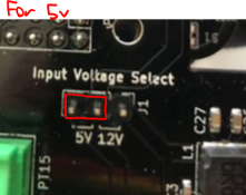
Flickering issue on 5V pixels

I don’t have an F33 :(View attachment 18301
Also, is the middle pin in the 5V/12V jumper supposed to be continuous with the v+ in from the psu or the outside?
Oh looks like he has revised and updated his board which would explain why your not seeing continuity to to J2 and the header. One side of the jumper will go to the PS input and looking at it closely it would make sense that it is the middle pin and the left one goes up to the components next to J2 and the right pin goes to the 12v buck converter.
 
Oh looks like he has revised and updated his board which would explain why your not seeing continuity to to J2 and the header. One side of the jumper will go to the PS input and looking at it closely it would make sense that it is the middle pin and the left one goes up to the components next to J2 and the right pin goes to the 12v buck converter.
The left pin is continuous with the V+ from the PSU and the middle pin is continuous up to the R3 resistor next to J2
 
Unless someone else can add some insights and the 5v/12v jumper is secure and making a good connection then you might need to go back to Daniel Kulp for advice.
 
Update - now my BBB isn't powering on when connected to the cape, even when supplied with separate USB power. It runs not connected to the cape, but for some reason won't start if attached. Power light is on and I see link lights on the NIC, but can't ping or navigate to the web interface. Maybe I'll try HDMI tomorrow if I find some time. I'm starting to think the board is haunted or cursed.

I really thought that the sequencing would be the difficult part of this pixel journey.
 
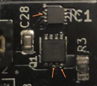
Do a close up inspection of the controller for solder blobs, had that cause a few issues in the past. You're looking for little balls of solder attached to things that don't quite look like they should be there.
 
Do a close up inspection of the controller for solder blobs, had that cause a few issues in the past. You're looking for little balls of solder attached to things that don't quite look like they should be there.
I don’t see any soldering issues, but not sure I would if it weren’t obvious.
 
I don’t see any soldering issues, but not sure I would if it weren’t obvious.
Slowly check over each of the IC pins and look for any pins that might be bridged over. Not just these two ICs but all of them.
Screenshot_20211005_125418.jpg
 
Back
Top