Navigation
Install the app
How to install the app on iOS
Follow along with the video below to see how to install our site as a web app on your home screen.
Note: This feature may not be available in some browsers.
More options
You are using an out of date browser. It may not display this or other websites correctly.
You should upgrade or use an alternative browser.
You should upgrade or use an alternative browser.
Flickering issue on 5V pixels
- Thread starter SamJ
- Start date
SamJ
New elf
- Thread starter
- #17
what resistor is on the outup of the kulp controller.
View: https://www.youtube.com/watch?v=H4pFvqIxkhQ&t=622s
I’m not sure how to even determine that.
Grozzy
Oh great, the idiot's back
- Joined
- Aug 16, 2018
- Messages
- 108
The Kulps definitely have level shifters on the outputs something like the 74act241 and have 100 Ohm resistors as well.
Flickering usually happens on the 12V pixels but with 5V all you will get is discolouration on white towards the end of your string so I would be swaying towards power supply or loose connections.
What size power supply are you using?
I would look at your pixel connectors into the kulp and check that they have been screwed in properly with the wire properly making contact and not screwed into the insulation. Also plug and unplug your extensions in and out multiple times .
Start with one set of pixels on one port and test it on solid red. Tap on the green connector plugs, your pigtail connections/extensions and the pixels themselves and see if you can induce the flickering.
Last edited:
I get 0V on the data line right now and the controller says that it’s still sending the RGBW test signal. That could be my cheap multimeter not being able to pick up the signal due to change rate.
Yeah that dosn't sound right, you should see a voltage between 5V and the data pin.
It should be around the 3v mark as that's an average of the data high and data low voltageYeah that dosn't sound right, you should see a voltage between 5V and the data pin.
Grozzy
Oh great, the idiot's back
- Joined
- Aug 16, 2018
- Messages
- 108
This is what 50 pixels look like all white with no power injection. Às others have said you should be getting a voltage on your data line but it will be quite low as it is data. Your meter might not be set to DC. Either way it's not an issue as you are clearly getting a data signal as your lights are lighting up. 10ft extension leads should work fine.


Last edited:
keithsw1111
Senior elf
Does the ground go from the first pixel back to the controller and from one pixel to the next pixel always. That is the most likely cause. Having the ground go back to the power supply and not to the board or the prior pixel will do this.
SamJ
New elf
- Thread starter
- #24
Update from my first round of tests this morning. I swapped in my second power supply and still having issues.
All outputs are set to 20%
1. Tested on solid red with a single strand of 50 pixels using just the 18" pigtails. This works fine on the 4 outputs I have wired up.
2. Tested on solid red with a single strand of 50 pixels using the 18" and a 5' extension. This has flickering on all 4 outputs.
3. Tested on solid red with a single strand of 50 pixels using the 18" and a 10' extension. This has flickering and color issues.
4. Tested on solid white with a single strand of 50 pixels using just the 18" pigtails. This has flickering.
My green connections seem solid - I can pull them off the board by the cabling. I did cut output 2 back to remove the tinning, but can't see that it made a difference compared to the others.
I'm still not seeing any voltage on the data line. This is supposed to be compared to ground at the end of the string, right? I get ~4.7V at the end of the string comparing V+ to ground so my multimeter is working.
Ground isn't looping back to anything. It comes in from the PSU and lands on the board.
I am powering the BBB from the USB input because it won't power up from the board. Could that be causing an issue since they aren't sharing a common ground through the PSU?
Last edited:
Grozzy
Oh great, the idiot's back
- Joined
- Aug 16, 2018
- Messages
- 108
Update from my first round of tests this morning. I swapped in my second power supply and still having issues.
All outputs are set to 20%
1. Tested on solid red with a single strand of 50 pixels using just the 18" pigtails. This works fine on the 4 outputs I have wired up.
2. Tested on solid red with a single strand of 50 pixels using the 18" and a 5' extension. This has flickering on all 4 outputs.
3. Tested on solid red with a single strand of 50 pixels using the 18" and a 10' extension. This has flickering and color issues.
4. Tested on solid white with a single strand of 50 pixels using just the 18" pigtails. This has flickering.
My green connections seem solid - I can pull them off the board by the cabling. I did cut output 2 back to remove the tinning, but can't see that it made a difference compared to the others.
I'm still not seeing any voltage on the data line. This is supposed to be compared to ground at the end of the string, right? I get ~4.7V at the end of the string comparing V+ to ground so my multimeter is working.
Ground isn't looping back to anything. It comes in from the PSU and lands on the board.
I am powering the BBB from the USB input because it won't power up from the board. Could that be causing an issue since they aren't sharing a common ground through the PSU?
You need to address why the BBB won't power off your Cape as your first problem.
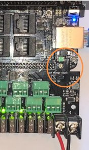
check that you haven't bent any pins on insertion, check that the 5v/12v jumper is not loose.(with the power disconnected remove the jumper and bend the pins a little bit out to make a tighter connection.)
With the USB power removed carefully measure the 5v voltage on the header pin marked 5v.
Last edited:
Grozzy
Oh great, the idiot's back
- Joined
- Aug 16, 2018
- Messages
- 108
Yes that is not right as it should be 5v.Pins are straight, jumper is good.
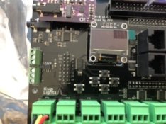
I’m getting .6V at either of the 5V pins - the ones to the left of the lcd, right?
View attachment 18299
There is minimal circuitry between your power input on the right and the rest of the circuit.
Unless you have blown the fuse or diode I am still leaning towards the 5v/12v jumper being the issue
With all the power off and your meter set to continuity mode (should beep when you touch the leads together) test from + on the right power input to the 5v/12v jumper and from + to J2 and + to the 5v on the header near the LCD.
SamJ
New elf
- Thread starter
- #28
I show continuity to the 5/12 jumper, but oddness to J2 and the 5V header. My meter reads 0 for continuity and those 2 register as ~.7Yes that is not right as it should be 5v.
There is minimal circuitry between your power input on the right and the rest of the circuit.
Unless you have blown the fuse or diode I am still leaning towards the 5v/12v jumper being the issue
With all the power off and your meter set to continuity mode (should beep when you touch the leads together) test from + on the right power input to the 5v/12v jumper and from + to J2 and + to the 5v on the header near the LCD.
Grozzy
Oh great, the idiot's back
- Joined
- Aug 16, 2018
- Messages
- 108


