G'day from Tassie

The ghosts I think were $1.50 from Woolworths.

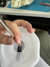
Again 1.2v and a single LED (at the top of the ghost). I shoved in 2x WS2811b strip LEDs at the bottom and hot glued them down. I ran only an ingress connector to them because a) they're very small and b) they make sense as a final piece per run.
1699294909544.jpeg


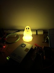
I was pretty concerned they wouldn't look very good, as the plastic diffused heavily during the day. However in the dark they looked great.
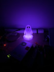
IMG_1498.jpgIMG_1501.jpgIMG_1502.jpgIMG_1529.jpg
 
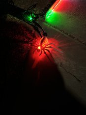
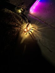
The scorpion, spider, rat and bird were also extremely cheap from Woolworths, I think around $2-3 each. These were fun - I had to work out custom pathing for them and I think I nailed it on the two I had time for. Sorry I don't have pictures of them all, but they are pretty much all the same design.

IMG_1531.jpgIMG_1530.jpg

The scorpion and spider were the two I got finished in time, and each had a single LED lighting both eyes, and 3 mounted twisted underneath to shine down as underglow. They looked pretty good, and I was very keen to light just their eyes up in my sequence along with the skull eyes on certain beats.
 
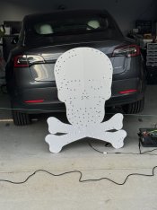
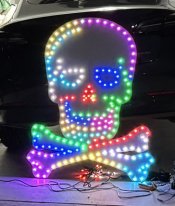
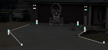
Skull and crossbones was to be my saving grace now I didn't have a matrix. Dad was kind enough to push the pixels for me, but I was sure he was doing it backwards. I didn't have time to argue, and it looked good lit up.

I checked the next day and it certainly was backwards 😂. I guess I could have flipped it in xLights. He also had difficulty stretching the bullet string to one of the spots around the jaw. I assume I could have skipped it on the software side, and it still looked pretty good if you weren't looking for it.

1699295124388.jpeg1699295153480.jpeg
 
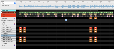
As mentioned, I spent a bit of time learning xLights at high speed and began sequencing a fun song called Hide and Seek. I was planning to put up the cool Korean animated video on the matrix (which looked very good in the preview in xLights, I guess due to my high pixel density). I had also built out a repeatable function (I forget the term) that allowed me to light up just the eyes on my props during the 'ding dong'. Given an extra day or two, I think I would have had something pretty cool to play here, especially given the simplicity of my prop setup and the ease of being able to grab an effect and drop it in across props to fill sections!

1699295228393.png

I was also planning to grab a few sequences from the Google Drive to play, but reading up now I expect there was more work than I had anticipated to prepare these to work with my setup.

1699295224414.png

Any custom sequences I build in the future, I plan to upload to the Google Drive for free under MIT license.
 
So that's my Halloween story. It was a failure, but I learnt a lot and wasn't really planning to do a show anyway. I'm pretty pleased with what I got done in the very short period between receiving my lights and deciding to go ahead and show time.

I am planning to complete and re-run my Halloween show next weekend or the one after, depending on how my schedule is looking. Unfortunately I've had too much travel this week (wrote most of this forum-post-turned-into-blog-essay on planes) to touch things at all beyond packing away my props.

In the next week I'm planning to build out proper controller boxes with good power runs and clean cable connections. I plan to use my existing coro runs to test out 1000 pixels per controller (not per output), which should allow for 70fps at max per run (https://kno.wled.ge/features/multi-strip/#esp32).

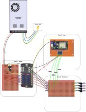
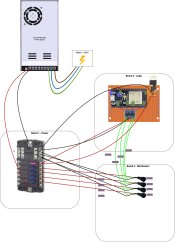
I've done a rough sketch of the physical controller layout.

controller.drawio.jpg

I'm very, very open to any suggestions on the controller, the show, the props or anything along the way. I'm concious it's year 1 and I'm biting off quite a lot here.

Thank you all for being so generous so far!
 
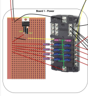
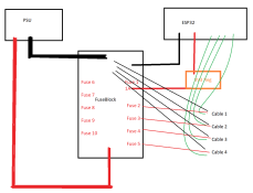
Woah nellie - what's going on with that fuse block there? You've got 12V coming on the input feeding the back end of a regulator and the 3.3V input of the ESP32.
All the internal connections between the fuses are connected as per my green lines here. You dont need the vero board to distribute the power.

1699307725790.png

Also - 60A fuses? That's alot of current which 1/ the cables wont handle, and 2/ the veroboard definitely wont handle.

My mudmap / suggestion:

1. Use very heavy (6mm2) cable from the PSU to the two large terminals on the fuse block.
2. Each fuse should be 5A or 7.5A going to pigtail wiring
3. Your 3.3V regulator should come from one of the fuse outputs
4. Pigtails should wire directly to the fuseblock positive and negative terminals. Dont use the veroboard. It wont handle the current.

1699308005926.png
 
Thank you for the feedback!

Woah nellie - what's going on with that fuse block there? You've got 12V coming on the input feeding the back end of a regulator and the 3.3V input of the ESP32.
I've actually never used a fuse block before, I assumed (incorrectly) I guess that the power went left to right across it as per my drawing. I guess it makes sense that it doesn't - why would there be two fuses in a row? Ok, so you feed the 5V (in my case) into the directly onto bottom of the fuse block, that makes sense. I guess this fuse block has way more outputs than I need then!

Does this wiring look more accurate (I haven't updated the fuse sizes or source wires to the fuse block, but good points thank you)?

1699318216639.jpeg

Also - 60A fuses? That's alot of current which 1/ the cables wont handle, and 2/ the veroboard definitely wont handle.
It did look high to me 😄. I was calculating on David's calculator, but I realise now I was doing it at 1000 per output, not per controller, which is a lot more reasonable:

1699315453142.png

That said, I would like to be able to support 1000 pixels on a single output if need be, which makes a 60A fuse look correct:

1699315499735.png

However now I'm having a look at my pigtails, it looks like they're 0.75mm2, which is 18AWG I believe. My back-of-the-envelope maths leads me to believe I can run about 16A (~300ish pixels) in there, assuming I'm injecting every 100 pixels or so, making each section 5.33A or so. I think my 1000 per output might have been reaching.

So I guess based on that, I can move down to 20A fuses on there?
 
Does this wiring look more accurate (I haven't updated the fuse sizes or source wires to the fuse block, but good points thank you)?
Much better! :) That wont end in smoke or tears unlike the first diagram :)

So I guess based on that, I can move down to 20A fuses on there?

Fuses are to protect the cable not to protect the devices attached to it. They should be rated such that they blow before the wire attached melts.

In a domestic situation, for a 10A appliance, it'll have 1mm2 cable on it, and smaller appliances will have 0.75mm2 cable.
0.75mm2 is good for up to about 8A, but in the pixel case, the voltage drop at that current will absolutely kill you. At 3m, you're already losing a volt, after which you'll start to see colour issues.

A 7.5A fuse is probably the most appropriate here. This would imply roughly 156 pixels, at full white, at 100%.
Real-world though, you can squeeze more out of it because the pixel wire resistance comes into play and each pixel does not draw it's full 48mA.

Now, if you were to do power injection, you'd use the additional fused outputs, and take those to the far ends or centres of the string, where needed.
That way each cable is protected to its maximum, but overall you get more. People will argue that it does mean that when one cable is overloaded and the fuse blows, it'll overload the other fuses. Yes, it will, You'll get a cascading failure. But you wont get a fire.
 
Much better! :) That wont end in smoke or tears unlike the first diagram :)


Fuses are to protect the cable not to protect the devices attached to it. They should be rated such that they blow before the wire attached melts.

Two of my least favourite things 😄 . Legend, thank you.

In a domestic situation, for a 10A appliance, it'll have 1mm2 cable on it, and smaller appliances will have 0.75mm2 cable.
0.75mm2 is good for up to about 8A, but in the pixel case, the voltage drop at that current will absolutely kill you. At 3m, you're already losing a volt, after which you'll start to see colour issues.

A 7.5A fuse is probably the most appropriate here. This would imply roughly 156 pixels, at full white, at 100%.
Real-world though, you can squeeze more out of it because the pixel wire resistance comes into play and each pixel does not draw it's full 48mA.

Now, if you were to do power injection, you'd use the additional fused outputs, and take those to the far ends or centres of the string, where needed.
That way each cable is protected to its maximum, but overall you get more. People will argue that it does mean that when one cable is overloaded and the fuse blows, it'll overload the other fuses. Yes, it will, You'll get a cascading failure. But you wont get a fire.
Thanks, that makes a lot of sense. Yes, I'm very happy to take failure over fire. 7.5A sounds workable with the gauge I'm committed to. Ok great, I can work with that. Thank you! I guess I'll go buy some extension wire, looks like Jaycar has it around $1.80 per metre, which is workable
 
Two of my least favourite things 😄 . Legend, thank you.


Thanks, that makes a lot of sense. Yes, I'm very happy to take failure over fire. 7.5A sounds workable with the gauge I'm committed to. Ok great, I can work with that. Thank you! I guess I'll go buy some extension wire, looks like Jaycar has it around $1.80 per metre, which is workable

Get yourself these, chop off the ends, cut to length, put on pigtails. 1mm2 for less than a dollar a metre.

3 core is good for normal extensions. If you're doing Power Injection, double one of them up on the negative to reduce resistance.
 
I had not considered doing power extension with... well power extensions 😂 . It seems pretty obvious now you say it. And they appear to be 10AWG inside, meaning less voltage drop. Perfect, thank you!

Do you normally do a solder + heatshrink for the joins? I want to ensure they're waterproof, given injection will likely be at spots in the weather.
 
And they appear to be 10AWG inside,
1mm2 = about 17AWG (1.1mm diameter). So slightly thicker than the pigtail wiring of 0.75mm2 / 18AWG (0.97mm diameter)

10AWG is massive 6mm2 cable (2.7mm diameter)

Do you normally do a solder + heatshrink for the joins? I want to ensure they're waterproof, given injection will likely be at spots in the weather.
Yes, I use that method for all my connections.
Others use the solder heatshrink tubes which do everything in one lot. I guess its up to your skill, patience and time as to which way you go.
 
I solder + double heat shrink. The inner heatshrink is small for the individual wires, then I use the sticky heatshrink over them all. But I am in the tropics.
I also double heat shrink but am in a place were we drop below 0 and can get a foot of snow for Christmas. :)
 
Hi all,

Figured I'd keep using this thread for updates. It's been a busy couple of weeks, and this weekend I'm actually hoping to set up some props. Got a few updates for the last couple of weeks.

Roof mounting

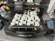
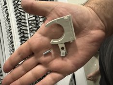
I started fiddling around with 3D printed clips for roof mounting. I bought some cheap Bunnings magnets while I waited for the ones I'd ordered online to come in, and the results were okay. I couldn't get a great fit, and push fitting them was a pain. I'm not a great 3D modeller, and I realised I didn't really have the time this year to do this.
1700722122377.jpeg

Turns out 25mm Deta clips from Bunnings and a trip down to Nuts and Bolts to get the guys to help me puzzle it out, and we got a good working magnet, clip, screw and nut combo. These magnets are STRONG, we already snapped to of them playing with them!

IMG_1872.jpgIMG_1873.jpgIMG_1874.jpg
 
Last edited:
Back
Top