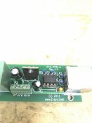
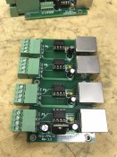
Help with ECG-PPR-A and ECG-PPD-C please?

farfree2

New elf
Joined
Jul 13, 2012
Messages
5
I confess, I've had these things for two years now and I still haven't figured out how to use them. I try each year in the fall for a day, and get mad that I can't figure them out and throw them back in the drawer again. I'm asking for help this year after looking around here, and a few other popular forum sites. I've been able to find/obtain the wiring diagram/layout and seen some comments on them, but not much information other than that out there.

My understanding was that I could place the ECG-PPD-C next to the controller maybe, run a cat5 or 6 line to the ECG-PPR-A and not be so limited to the 10-15ft that I'm currently limited to before I have to use a null pixel. I've been using WS2811 12v Pixels lately and have some luminaries further out in my yard that I would like to run a Cat6 line to underground so wires aren't showing, but before I bother, I need to figure out how to get these pixel extenders to work. I've put a multimeter on the receiving end (ECG-PPR-A) of this when test hooking it up, I see ground and 12volts come across, but I can't seem to figure out which port the data is supposed to come through.

I see a lot of comments out there about being able to put a little 5v power on the receivers out there, but nothing on 12v. Its completely ok if I need to make sure I have a power source out there at the receiving end, as I plan on needing one as I add displays in the future, just need to know how to properly use these and information seems to be scarce.

Anyone out there familiar with these? More information would be greatly appreciated! Thank You.
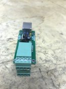
Photo Dec 06, 9 00 57 PM.jpg Photo Dec 06, 9 01 09 PM.jpg Photo Dec 06, 9 01 36 PM.jpg
 
I think I have some of the receivers in my "not likely to be used" pile somewhere.

The outputs of the receiver boards will be coming from pins 2 and 3 of the 8 pin chip, via resistors. Maybe you can trace where they go to on the green connector?

I'll try to dig mine out today and have a look for you. I can sympathise with you on the lack of information & support.
 
Firstly how many pixels do you intend to run from each receiver - cat 5 is only good for about 1 amp then you need an external power supply. Sounds like you have 12v going to the transmitter already from your controller output. Note P1 on the transmitter powers the board electronics - without P1 powered by at least 7v you will not get pixel data transmitted up any of the cat5 cables.

Try this post from a couple of years ago to get started https://auschristmaslighting.com/th...gram-pinout-for-ecg-ppd-d-and-ecg-ppr-a.8213/
BUT, what you intend to do at the receiver will determine which jumpers are needed and where and what power supplies you are using (do not want to supply pixels with the wrong voltage or over volt the chip on the receiver).

When comparing to the schematic - the first photo of the receiver double stack connector - bottom row left to right is terminals 5 to 8. These are the pixel terminals, (5 is gnd - same as transmitter port) Top row is left to right terminals 1 to 4. The jumper between 3-4 connects the output of the onboard 5v regulator to the pixel terminal. Not needed if powering the pixels with 12v ??

The second photo of the 5 way terminal shows a bridge between 1-2 which is connecting the voltage delivered by the cat5 onto the +v pixel terminal. What you need is jumpers between 2-3 and 4-5 which would power the receiver electronics with 5v from the regulator - obtained from the cat5.
(Eddited to correct mistake with terminal numbering).

Hope this helps.
 
Last edited:
I found mine this morning and yanked the ICs and regulators off them.

@prof seems to have a handle on them. I found them confusing to be honest.
 
oh I had a good handle on them, they just didn't work as advertised.

Wasn't a good sign when Ed said there was a board fault that rendered half the ports useless on the 4 port PPD, but even the 2 remaining ports never worked well at all. Sadly I bought up big for a project rather than testing a set first.
 
Thanks for chiming in everyone! Really appreciate the info. To clarify;
1. Running over CAT6
2. Distance is maybe 30ft at most
3. I know they were going to power well, which was fine, I have a 12volt supply nearby to draw power from, just couldn't get the signal at the receiving end
4. My understanding is that the 5v capability at the receiving end is pointless if I'm running 12volt's....right?

As I will obviously not be implementing these this season yet again, considering the responses from everyone, I am not the only one that wasn't a fan of these. Quite alright, I can live with the loss. Not the end of the world. I'll try not to go too far off subject of the thread, but what would everyone suggest moving to for extenders that you have already worked with and works well in your current sequence setup? Plan on implementing maybe a matrix and some more snowflakes next year where an extender or two would be preferred as opposed to null pixeling it. What say ye oh wise ones?!?!
 
Edited my previous post to fix a mistake with terminal numbers after going back and re reading the post from 2015. This powers the receiver (using the onboard regulator) via the 12v coming up the cat5. Removing the jumper from 3-4 on the stacked connector removes the onboard 5v from the pixel power terminal (8). You have not said how many lights you want to run. That will determine how the 12v power supply is connected - are you using a seperate psu to power the pixels or are you going to power them from the same suply coming up the cat5 (limited to about 1A).
 
Back
Top