Kulp K8-B on-board ports not working

pilotman06

New elf
Joined
Dec 13, 2020
Messages
13
Hello everyone,

First thank you for your help and input. I am new to this and opted for a Kulp K8-B with a beaglebone black with FPP pre-installed for my first attempt. Unfortunately after setting everything up, I am unable to get the 8 on board ports to function correctly. With a pixel string plugged in to any of the 8 ports, they will not light up when using the on-board testing menu, the test menu via FPP, or trying to run any of my sequences. In an attempt to check voltage when touching my multi-meter to the screws in the pixel connection port, I have randomly gotten a few pixels to light up random colors. Generally only the first 1-3 pixel modules. They are unresponsive to FPP commands and they only turn off with a power disconnect.

To Troubleshoot I was able to connect a smart differential receiver board to the port 9-12 plug on the K8-B. Both the K8 and receiver board are connected to the same power supply. With the string connected the the differential board I am able to get them to fully function in every way. The test button on the receiver board works, the test options via the on board buttons/screen works, the test function on FPP works, and my sequences will run. At one point I tried 3 strings on the differential board and 1 string on the K8 port, the 3 differential strings worked, while the K8 string did not. Kulp sent me a replacement K8-B board and unfortunately it is responding the same way. It seems odd to me that two board would be defective in the same way but I am not sure what I may be doing wrong to cause this issue. I am showing 12.8v at the power supply, 12.8v at the differential, 12.7v at the differential pixel connection, 12.5v at the K8-B power input, and 12.5v at the K8-B pixel connection port. FPP is report 11.9V In. In previous troubleshooting my multimeter showed ~12V at the end of the pixel string that was connected to the K8-B but not responding.

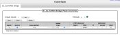
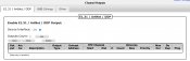
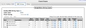
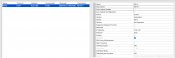
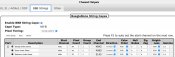
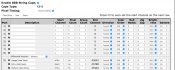
Attached is my X-lights controller settings. and my FPP BBB settings when it is not functioning on Port 1, and when it IS functioning on port 9. For Port 1 I use #10:1 start channel with 3 strings (Garage Under Eaves, Entry Under Eaves, and Bedroom Under Eaves) connected in sequence all specified to Controller Port 1. For Port 9 I use #90:1 start channel. I don't think it is applicable but I inject a fresh power source after 84 modules (252 pixels) in either configuration.

I would love to find what I am doing wrong in my setup, otherwise I have two non-functioning K8-B boards. Thank you again!
 

Attachments

  • Xlights Controller.jpg
    Xlights Controller.jpg
    308.2 KB · Views: 39
  • K8-B port 1.jpg
    K8-B port 1.jpg
    461.5 KB · Views: 38
  • K8-B Port 9.jpg
    K8-B Port 9.jpg
    715 KB · Views: 41
Last edited:

BAZMick

Full time elf
Generous elf
Joined
Nov 26, 2019
Messages
483
You've got a pixel count of 0 on the string config. Change that to how ever many pixels are on the string for port 1 then connect the string to port 1.
In xlights I would suggest you change your universe count to say 10 in the beginning.
Read up on the 101 manual about channels and universes. Universes are a group or block of channels
 

pilotman06

New elf
Joined
Dec 13, 2020
Messages
13
You've got a pixel count of 0 on the string config. Change that to how ever many pixels are on the string for port 1 then connect the string to port 1.
In xlights I would suggest you change your universe count to say 10 in the beginning.
Read up on the 101 manual about channels and universes. Universes are a group or block of channels

Thanks for the reply! I have only one string. When it is on port 9, I have nothing on port 1, thus the 0 on port 1. And vice versa if I have them connected to port 1, my port 9 shows 0. But only works if its configured to port 9. I did notice I need to update my universe start at 10, but I assume that isn’t creating the fault.
 

pilotman06

New elf
Joined
Dec 13, 2020
Messages
13
You've got a pixel count of 0 on the string config. Change that to how ever many pixels are on the string for port 1 then connect the string to port 1.
In xlights I would suggest you change your universe count to say 10 in the beginning.
Read up on the 101 manual about channels and universes. Universes are a group or block of channels

I updated my xlights config to have my string start at #1:1 on port 1 and my start universe for the controller to still be 1. Uploaded the outputs, verified in FPP, saved, shut down, plugged lights into port 1, booted up, verified BBB string showed all pixels on port 1, still nothing. Tests and sequences don't illuminate any pixels. See Attached FPP BBB string screenshot. Any ideas? Thank you again!
 

Attachments

  • K8-B Port 1 Universe 1.jpg
    K8-B Port 1 Universe 1.jpg
    256.6 KB · Views: 24

BAZMick

Full time elf
Generous elf
Joined
Nov 26, 2019
Messages
483
Silly question but you have filled in the inputs page in FPP? You can do this from xLights, "upload inputs"

Screenshot_20210119-082625.png

If you get no joy after this then wait till about 8pm AEST and jump into chat here and you should be able to find somebody to connect on zoom with to sort you out.
Alternatively you could try the X lights zoom room.
This problem sounds like a simple setting or config that we've all overlooked
 

tooms

12v4life
Joined
Jan 2, 2015
Messages
208
Location
Kalgoorlie
I would delete the channel outputs if you have no other controllers connected to it, I believe with the setting you have enabled it's trying to send universe 1 via the ip address of the controller you've specified.
 

BAZMick

Full time elf
Generous elf
Joined
Nov 26, 2019
Messages
483
Channel inputs, change number of universes to 10 but keep the size at 510.
Channel Outputs, like @tooms said delete the e131 entry you have there, uncheck the active box, or uncheck the Enable e131 output. BBB strings page is where you need to enter the details for the pixel string.

Do some research on universe and channels please? Having 510 universes set to output is probably overloading the controller. I'd say only a handful of people on this forum would be outputting more than 260k+ of channel data and they wouldn't be doing it all from one controller.

Think of your show as a sports stadium, the IP address of the controller is the gate number which is closest to your seat. Next is the universe number which is the row of seats (pixel string), and finally the channel number is your seat (single led in the pixel string). It's just an addressing system.
 

pilotman06

New elf
Joined
Dec 13, 2020
Messages
13
I would delete the channel outputs if you have no other controllers connected to it, I believe with the setting you have enabled it's trying to send universe 1 via the ip address of the controller you've specified.

Thank you for your continued advice! I've updated my settings to have 2 Universes starting at #1. 185 modules with 3 nodes each makes 555 channels which would need some of a 2nd universe. I've deleted and deactivated E1.31/ArtNet/DDP under Channel Outputs. My string is now on port 1 and i have it set to #1:1 on port 1 in xLights. Unfortunately still nothin... Test modes don't work nor sequences. I move it back to port 9 via the smart differential receiver board, update it to port 9 in xlights, and everything works. Attached is FPP screenshots when plugged into port 1.
 

Attachments

  • Channel Inputs 2 Universes.jpg
    Channel Inputs 2 Universes.jpg
    309.3 KB · Views: 16
  • Channel Outputs Blank.jpg
    Channel Outputs Blank.jpg
    336.6 KB · Views: 15
  • Channel Outputs Updated.jpg
    Channel Outputs Updated.jpg
    516.7 KB · Views: 15

Danielr

Lights On Botanical
Generous elf
Joined
Jul 13, 2019
Messages
98
The best place to go would be to jump on zoom so they can see you screen live. In Xlights I would also tick the check boxes for auto layout models and auto upload configuration in the controller tab.
 

BAZMick

Full time elf
Generous elf
Joined
Nov 26, 2019
Messages
483
Are the LEDs above the fuses lit indicating you've got power to the ports, measure the voltage and see if it's the correct voltage for the string. Sorry I think a step back is needed to double check the basics. Are the - Data and+ wires in the correct terminals. You mentioned in the first post you had up to 3x pixels flickering when checking voltage with a multi meter?
 

pilotman06

New elf
Joined
Dec 13, 2020
Messages
13
Are the LEDs above the fuses lit indicating you've got power to the ports, measure the voltage and see if it's the correct voltage for the string. Sorry I think a step back is needed to double check the basics. Are the - Data and+ wires in the correct terminals. You mentioned in the first post you had up to 3x pixels flickering when checking voltage with a multi meter?
Yep, all fuses have LEDs lit up. To continue to troubleshoot I took power from port 1 on the kulp board and data from port 9 from the smart differential receiver board, and the lights worked great. Then took power from port 9 and data from port 1 and not good.

This time however I got 45 modules to illuminate, most white, some other colors. Changing tests modes in FPP may distort the color in 1 or two of them, but never the color selected. Can't turn them off unless I pull power from the power supply. Such as when I went to test mode red, the first module turned green, and when I went to green, it turned blue. But the remaining modules stayed white. Test modes worked as expected if using port 9 data.

Multimeter showed 12.5V at the pixel connector on the smart receiver board, and 12.3V at the Kulp port 1 pixel connector.
 

BAZMick

Full time elf
Generous elf
Joined
Nov 26, 2019
Messages
483
. Then took power from port 9 and data from port 1 and not good.

This time however I got 45 modules to illuminate, most white, some other colors
That's a V- problem, did you connect V- between the Smart Receiver and the Kulp board with this test?
Check with the multi meter if you have continuity between the V- on ports 1-8 and the power supply V- and the V- on the power input of the Kulp board?

Edit: do these checks with no power on of course!
 

pilotman06

New elf
Joined
Dec 13, 2020
Messages
13
That's a V- problem, did you connect V- between the Smart Receiver and the Kulp board with this test?
Check with the multi meter if you have continuity between the V- on ports 1-8 and the power supply V- and the V- on the power input of the Kulp board?

Edit: do these checks with no power on of course!

Sorry I didn't reply sooner, just got back home to check. I didn't directly wire the V- between the Kulp and smart receiver pixel connectors but I just checked and I have continuity throughout. V- from every kulp pixel plug to the primary V- on the Kulp board, V- at the power supply, V- at the smart receiver and at every smart receiver pixel connection. Same goes for V+, continuity between all V+ connections. Thanks for the help as I hadn't checked continuity yet.
 
Top