Mini RGB Bollards

David_AVD

Grandpa Elf
Community project designer
Generous elf
Joined
Jun 12, 2010
Messages
4,695
Location
Victoria Point (Brisbane)
I bought a couple of solar garden lights from Bunnings the other day. The "wood look" version (pictured below) is only $2, while the stainless steel tube version is $5. They are both intended for outdoor use (hence the solar bit!), but the "wood look" tube is made out of some composite material and I'm not sure how long they'd last outdoors.

I bought these samples as they looked ideal for using as a low cost casing for LED lights and/or controllers. You couldn't buy an empty enclosure for $2 - $5.

Anyway, the tube is 65mm diameter (O/D) x 180mm high. Even with the plastic spike and top cap installed, there is approx 140mm of usable height in the tube. The spike base has one ~7mm hole and a couple of ~3.5mm holes in it that wiring could be passed though.

The solar cell, LED, battery and electronics are all mounted onto a black plastic disc that locks into the top cover. All items can be removed in seconds with a pair of wire cutters, leaving you with a consistent way to mount your new LED PCB or RGB pixel, etc.

MGalleryItem.php


MGalleryItem.php
 
OK, I thought I'd work on the Bunnings ($2 / $5) solar bollard lights some more.

I've designed a small PCB (40mm x 40mm) that drops in the recess where the solar cell would normally live. It's a single sided board that uses all SMD parts.

It's powered from 12V, uses a WS2801 IC and has 3x 5050 LEDs set 120 degrees apart in a 13mm radius.

The power and data connections can be made through the back of the board as I've lined them up with the two existing cutouts in the plastic carrier.

As you can see, it also has a 3mm hole in each corner for ease of mounting in other applications.

I'll get some sample boards made up in late January and see if it all works.

MGalleryItem.php
 
Looks good David...

You can also take a look on "members project". I made 2000 units similar ones 3cmx3cm powered with 12volts too. (same PCB for 3 x SMD 5050 with embedded option to power flood SMD 5050 LED too.), 2 in one module.

I need to continue the description of the flood built too, on the section, as i'll get some free time... Soon...

Works great now since 2 months...


If i can , one comment : you don't really need the transistors to power the 5050. You can charge the WS2801 up to 3 x 5050 SMD without any problem and no warm at all; means 60 ma per output... This is what i made....
The datasheet is not really complete on all specs...

I think this year will be really a big year explosion for pixel projects....
 
Got 18 of the "wood like" bollards now. That's enough for 16 units with 2 spares. Bunnings put them on clearance for $1 each.

I have built up the sample pixel PCB. Just need to hook up an SPI driver and test it before making the other 15.
 
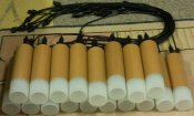
I thought it was about time I did some more with this project. Here's about 20 RGB pixel boards nearly completed:

apc694.jpg
 
For the cables, I bought black 4 pin extension leads from Ray Wu. I got 100 each of the 1.5m and 3.0m lengths. I did this to make sure I'd have enough for all my projects without having to buy more later, as new stock may not be exactly the same. I think I worked out that they were only 0.4mm CSA. Heavier gauge would be much better of course.

For these bollards, I cut the 1.5m ones about 200mm from the female end. The longer male tail is the input and the short female tail is the output. This way, they are all the same and I can just chain them together. I'll use a spare female connector with the cable end sealed off to plug into the last one in the chain. That will stop water, ants, etc from getting in there.

The supply voltage is 12V and in the video I'm driving them with a PIXAD8 and my da_E131 in chaser mode. If I put all 16 unit on full white, you can notice a very slight tinge of pink on the end units. This is due to the voltage on the end ones only being about 10V, compared with 12V for the first one. If I make more, I'd look are designing the circuit a little differently or perhaps use a slightly higher supply voltage to compensate for the drop.

I tried increasingly longer cables from the PIXAD8 to the first pixel and thought that 4.5 metres was still ok. When I looked closer, there was some phantom flickering in adjacent boards. So I've dropped it back to 1.5m and all is stable. I don't have any 1.5m extensions left here at home to see if 3m is acceptable. I will also test my little pixel extender PCB when I get a chance to see if that will clean up the data and clock signals on longer runs.

Overall I'm quite happy with them as they're another item for my PnP (Plug 'n' Play) display . :)
 
Back
Top