Need a 5v dimmable controller that is + controlled

LA0

New elf
Joined
May 8, 2013
Messages
16
Hi everyone..

I've been tearing my hair out trying to find or come up with some kind of controller that can output 5V + control signals.

All the typical DC controllers I see are negative switching whereas I need positive switching.
Most controls have a common positive and have multiple negatives, I need the opposite.

I don't need the controller to be high current, as it is just feeding some microcontroller analog pins (It will be acting like a potentiometer).

Ideally I would like 16 channels.

If anyone has some Arduino code that can dim with 5v I'd be happy with that too. Whatever I can find...
Or if I could hack one of the common anode type dumb RGB controllers and turn it into a common cathode. I don't know....

Anyway thanks for any help.
Take care everyone.
 

Notenoughlights

400,000+ twinkly lights
Joined
Oct 16, 2016
Messages
658
Location
Christchurch, New Zealand
I've got some Arduino code that allowed a huge number of dimming channels. I'll see if I can locate it after work for you. I didn't write it but modified it to work for what I wanted. I was running 48 pwm/dimming channels across 2 Arduino megas many years ago for my lights.
 

LA0

New elf
Joined
May 8, 2013
Messages
16
I've got some Arduino code that allowed a huge number of dimming channels. I'll see if I can locate it after work for you. I didn't write it but modified it to work for what I wanted. I was running 48 pwm/dimming channels across 2 Arduino megas many years ago for my lights.

If you can find the code, that would be awesome!!

Thank you so much!
 

David_AVD

Grandpa Elf
Community project designer
Generous elf
Joined
Jun 12, 2010
Messages
4,682
Location
Victoria Point (Brisbane)
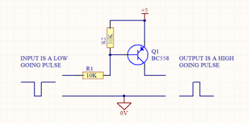
You could always use a standard controller with either resistors and PNP transistors, or resistors and ICs to get the signal you want.
 
  • Like
Reactions: LA0

LA0

New elf
Joined
May 8, 2013
Messages
16
You could always use a standard controller with either resistors and PNP transistors, or resistors and ICs to get the signal you want.
I have thought of that, but am just not really sure where to start admittedly...

I have thought about taking any of the generic 24-27 channel dumb dmx controllers, or one of the Hanson boards and making some kind of PCB to modify the output.

The nice thing is that a lot of those dumb controllers can run at 5v. So I guess my question is how do I flip the output?
How do I take a common anode arrangement and make it into a common cathode setup instead?

So instead of: "V+ | -1 | -2 | -3"

It should be: "V- (gnd) | +1 | +2 | +3"

I've looked at different transistor arrays IC's and whatnot, but I am just not sure where to begin..

I can solder and assemble boards well, but I find myself struggling with this, and figuring out the best way to go about it.

Anyway thanks for the advice / help.
 

LA0

New elf
Joined
May 8, 2013
Messages
16
Thank you so much for that...

I noticed the BC558 has been discontinued. Would the BC556ABU be a good alternative? It seems to have pretty close specs.

Now all I need to do is convert the PWM into an analog signal which @AAH pointed out to me in a PM, as I reached out to him regarding controller possibilities and modifications.

I was looking into PWM DAC IC's but can't really find any that will work well with this without too many additional components. (I would like to avoid the use of op amps if at all possible).

I think my plan now will likely be to use one of the Hanson DMX boards unmodified , just using the above PNP circuit along with some kind of RC filter.

Does anyone know good capacitor and resistor values for a RC filter for this use case?

Thanks for the help!
 

TerryK

Retired Elf
Joined
Feb 9, 2020
Messages
655
Location
West Central Ohio
The BC556 can be used in place of a BC558. The BC556ABU part number is actually a BC556A supplied in bulk. If you web search for the Fairchild BC556A datasheet it details specs for everything from the BC556 through BC560.

Another thought or two: a PWM to analog converter is in its simplest form nothing more than an integrator. A low pass filter as it were. At some point you will need to determine how responsive the analog output will be. There is a 'Catch 22' here though. The more responsive the converter the higher the amplitude of the 'waves' one will see riding at the top of the analog output voltage.
The Op Amps you had mentioned you would prefer avoiding serve several purposes. Aside from level shifting and amplification, buffering. Their high input and low output impedances isolate the filtering circuitry from the 'downstream' load and if implemented, the 'upstream' as well.

I would suggest some web searches on PWM to Analog converters; how they work, schematics, component selection/values, and such. This will help you better understand how to build one.
 
  • Like
Reactions: LA0

LA0

New elf
Joined
May 8, 2013
Messages
16
The BC556 can be used in place of a BC558. The BC556ABU part number is actually a BC556A supplied in bulk. If you web search for the Fairchild BC556A datasheet it details specs for everything from the BC556 through BC560.

Another thought or two: a PWM to analog converter is in its simplest form nothing more than an integrator. A low pass filter as it were. At some point you will need to determine how responsive the analog output will be. There is a 'Catch 22' here though. The more responsive the converter the higher the amplitude of the 'waves' one will see riding at the top of the analog output voltage.
The Op Amps you had mentioned you would prefer avoiding serve several purposes. Aside from level shifting and amplification, buffering. Their high input and low output impedances isolate the filtering circuitry from the 'downstream' load and if implemented, the 'upstream' as well.

I would suggest some web searches on PWM to Analog converters; how they work, schematics, component selection/values, and such. This will help you better understand how to build one.

Thanks for the help, I found the LTC2644CMS-L8#PBF specifically which I think may work well for my use case. It is a 2 channel PWM DAC chip that can take 5v PWM signals. The other thing is that it is 8 bit I think that should be good considering DMX is 255 8-bit too, so that should be the right resolution? I think...

The one thing I got hung up on is that it only outputs a maximum of 2.5v.. I wanted to avoid op amps because I have always found them somewhat intimidating and I don't fully understand them (But I would like to).

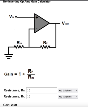
So after doing some research, I've come to the conclusion that I need a non-inverting op amp configuration.
I used this calculator to calculate the right resistors for the gain.

I think I want a gain of 2... As 2.5v x 2 = 5v.. So a gain of 2x is what I need.. Right?
The calculator told me I need two 10k ohm resistors.

I also used this calculator to make extra sure.
Screenshot 2022-01-28 at 4.21.30 PM.png

So my plan now is to use the PWM inverting circuit that @David_AVD provided me with above, feed it into a 8-bit PWM DAC like the one above, then use a non-inverting op amp to give me a 2x gain bringing the DAC up to 5v.

Does all of this sound ok?
Am I missing anything?

Thanks for all the help everyone!
This has been a good learning experience for me and I really appreciate it.

EDIT: To add, what would be a suitable op amp for this? What should I look for in op amps?
 
Last edited:

TerryK

Retired Elf
Joined
Feb 9, 2020
Messages
655
Location
West Central Ohio
The LTC2644 has a PWM range of 30 to 100K Hertz so the PWM source will need to be within those limits. To avoid aberrations in the output it will need a continuous PWM input. The datasheet tells how the IC reacts if the input goes away. Using an Op Amp with a gain of 2 would give you a 0-5 output. You may find however that a small adjustment in gain or offset might be advantageous. These are easily accomplished and a web search will show you how. A thought here is if you invert the PWM and use a non-inverting Op Amp circuit, you could, not invert the PWM and use an inverting Op Amp and (I think) get the same output. If you look at the typical application schematic on page 17 of the datasheet, there is an optical isolator on the input. These typically do not care whether they are connected to a sinking or sourcing output. Regardless how the circuit evolves it should be 'mocked up' to determine that the output is what one wants.

A suitable Op Amp can be found by searching any electronic distributors, Mouser for example. 100KHz is easily within the working range of most if not all of them. Of note is most Op Amps like to use 'mirrored' supplies, that is +5 and -5 or say +12 and -12. Inputs and outputs move around 0. Op Amps can be and are used with single ended supplies but their output has a tendancy to become non-linear as the power rails are approached (which is also true with 'mirrored' supplies). Some handle this better than others, that is, depending upon design, some can move closer to the power rails before becoming non-linear.
 
Last edited:
Top