jstjohnz
Apprentice elf
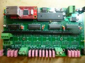
I have just assembled the first prototype of a new version of the E680 pixel controller, somewhat un-cleverly named the E681. Nothing revolutionary, just a re-work of the hardware to add some requested features.
New in the E681:
Same 16-string capacity as the E680. OK, I guess that isn't new.
Single PC Board 6.8" x 4.1". Quite a bit larger than the E680.
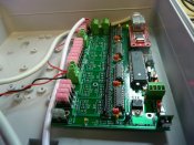
Designed to mount one (and power supply) or two (external supply) in a standard CG-1500 enclosure. Makes it easy to use the very inexpensive CG-1500 enclosure as a housing for your controllers. There's room for an E681, a power supply, and a small ethernet switch. Or 2 E681s if your power supply is external. Mounting holes mate directly with CG-1500 standoffs.
DC-DC converter for controller power means the controller can operate off of any pixel voltage. No more heat sink! Now you can power the controller from the pixel power supply regardless of the voltage of your pixels. Eliminates the need for a separate supply, although that option is still available.
Regulated +5VDC output for powering a small ethernet switch There is an on-board power connector that can supply 5VDC to a small ethernet switch such as the Trendnet TE100. The switch ports allow easy daisy-chaining of multiple pixel controllers (without having to worry about supplying AC power to the switch's wall transformer).
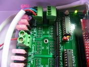
3.5mm "Euro Style" pluggable screw terminal blocks for pixel connections. Eliminates the crimp pins! Pixel connections attach to pluggable screw terminal blocks. Shamelessly lifted from (and compatible with) the PIXAD8.
Upgraded pixel power input connectors, will handle up to 32 amps on each side, or 64 amps total.
Individual mini plug-in automotive-style blade fuses on each pixel string output.
Optional buffer ICs for driving pixel clock and data lines. If not needed, a set of dip jumpers allows for driving pixels directly from the CPU pins. The optional buffer chips allow for a full +5V drive capability when needed. Selectable +3.3V or +5V on *each* buffer chip for compatibility with both 3.3V and 5V pixels.
Pluggable resistor networks in all clock and data lines for enhanced line driving capability. Some pixel types can be driven over longer distances if a series resistor is used in the clock and data lines. By using pluggable resistor networks, it's easy to change these when needed for a particular application.
Pictures soon....
New in the E681:
Same 16-string capacity as the E680. OK, I guess that isn't new.
Single PC Board 6.8" x 4.1". Quite a bit larger than the E680.
Designed to mount one (and power supply) or two (external supply) in a standard CG-1500 enclosure. Makes it easy to use the very inexpensive CG-1500 enclosure as a housing for your controllers. There's room for an E681, a power supply, and a small ethernet switch. Or 2 E681s if your power supply is external. Mounting holes mate directly with CG-1500 standoffs.
DC-DC converter for controller power means the controller can operate off of any pixel voltage. No more heat sink! Now you can power the controller from the pixel power supply regardless of the voltage of your pixels. Eliminates the need for a separate supply, although that option is still available.
Regulated +5VDC output for powering a small ethernet switch There is an on-board power connector that can supply 5VDC to a small ethernet switch such as the Trendnet TE100. The switch ports allow easy daisy-chaining of multiple pixel controllers (without having to worry about supplying AC power to the switch's wall transformer).
3.5mm "Euro Style" pluggable screw terminal blocks for pixel connections. Eliminates the crimp pins! Pixel connections attach to pluggable screw terminal blocks. Shamelessly lifted from (and compatible with) the PIXAD8.
Upgraded pixel power input connectors, will handle up to 32 amps on each side, or 64 amps total.
Individual mini plug-in automotive-style blade fuses on each pixel string output.
Optional buffer ICs for driving pixel clock and data lines. If not needed, a set of dip jumpers allows for driving pixels directly from the CPU pins. The optional buffer chips allow for a full +5V drive capability when needed. Selectable +3.3V or +5V on *each* buffer chip for compatibility with both 3.3V and 5V pixels.
Pluggable resistor networks in all clock and data lines for enhanced line driving capability. Some pixel types can be driven over longer distances if a series resistor is used in the clock and data lines. By using pluggable resistor networks, it's easy to change these when needed for a particular application.
Pictures soon....