Navigation
Install the app
How to install the app on iOS
Follow along with the video below to see how to install our site as a web app on your home screen.
Note: This feature may not be available in some browsers.
More options
-
2026 Mini Christmas Light Expos - RSVP Now
Perth Mini: 13 June | Melbourne Mini: 4 July | Sydney Mini: 4-5 July -

You are using an out of date browser. It may not display this or other websites correctly.
You should upgrade or use an alternative browser.
You should upgrade or use an alternative browser.
Pixel controllers - local repair in Aus?
- Thread starter janastas
- Start date
TerryK
Retired Elf
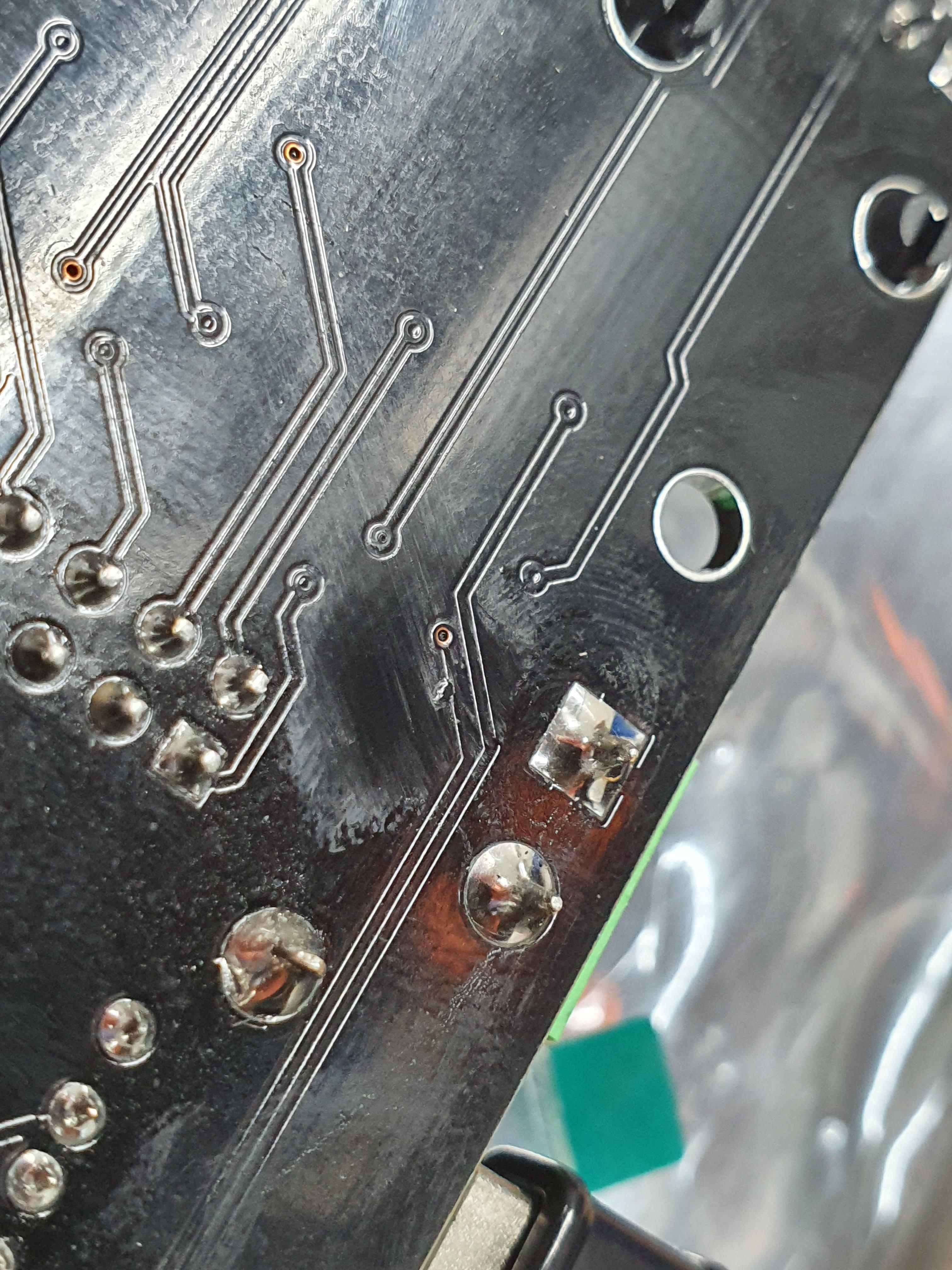
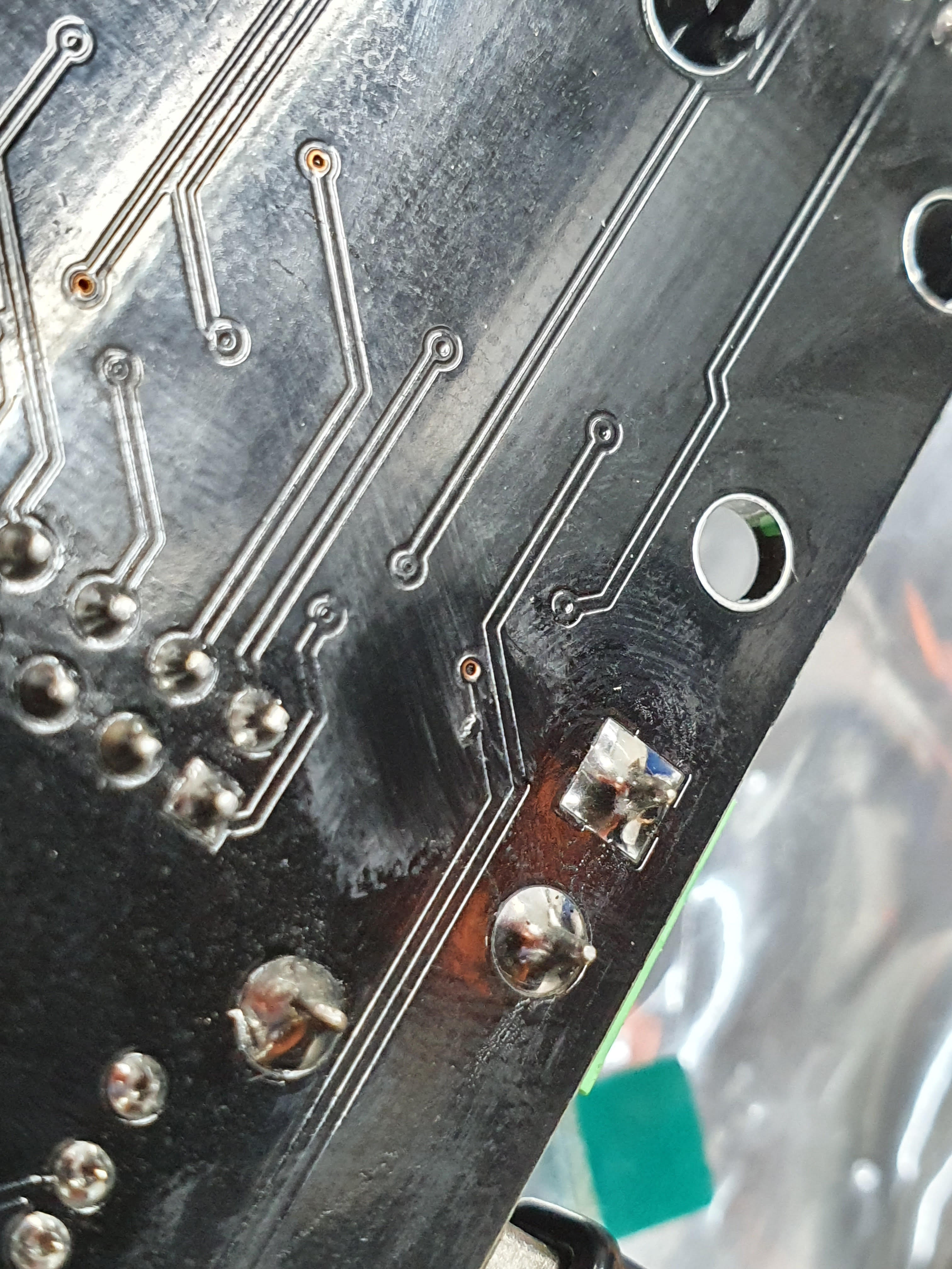
The GND terminal (the square pad) looks a bit iffy I think, rather difficult to say, can see a circular ridge around the pin in one graphic but not the other. Post #19, when you applied power to the soldered pins, did you do both or just one?

Also wondering, is the trace damaged where the red circle is?
Also wondering, is the trace damaged where the red circle is?
janastas
Full time elf
- Joined
- Nov 30, 2020
- Messages
- 120
- Thread starter
- #18
The GND terminal (the square pad) looks a bit iffy I think, rather difficult to say, can see a circular ridge around the pin in one graphic but not the other. Post #19, when you applied power to the soldered pins, did you do both or just one?
View attachment 16826
Also wondering, is the trace damaged where the red circle is?
When I applied power to the pins it was postive wire to positve pin and negative to negative.
Yeah I did notice that red circle but wasn't sure what to make of it.
Mind you I have a smart receiver and and power8 distro board in the same controller box and they're still working fine so don't think it was a power issue.
Sorry yes you're right it does pull the wire up to secure them to the terminal.
What I'm saying is that when you use a screw driver to tighten the connection you have to apply quite a bit of pressure while turning for the terminal to pull up on the wire.
If you don't apply pressure on screw driver while turning the terminal doesn't pull the wire up.
No.
You need to Lefty loosey(anticlockwise) the screw terminal without a wire inserted to open it up, then put the wire in, and Righty Tighty(clock wise) to clamp down on them.
The terminals are shipped as closes so they do not rattle, and have the screw fall out.
janastas
Full time elf
- Joined
- Nov 30, 2020
- Messages
- 120
- Thread starter
- #20
No.
You need to Lefty loosey(anticlockwise) the screw terminal without a wire inserted to open it up, then put the wire in, and Righty Tighty(clock wise) to clamp down on them.
The terminals are shipped as closes so they do not rattle, and have the screw fall out.
Sorry my terminology was shocking after reading my post, yes I did exactly what you said above.
Sorry my terminology was shocking after reading my post, yes I did exactly what you said above.
Just making sure

Had you had a reply yet from kulp? There's a few here willing to help to have a look.. So depends on your location.. What is your location?
janastas
Full time elf
- Joined
- Nov 30, 2020
- Messages
- 120
- Thread starter
- #22
Just making sure
Had you had a reply yet from kulp? There's a few here willing to help to have a look.. So depends on your location.. What is your location?
Haven't heard anything back yet from kulp so will try email again.
Mind you I emailed them on Friday night our time so really they've only had monday and might not have seen the email as yet.
I'm in the norther suburbs of melbourne, so far I've had a few interstaters offer to help out which is greatly appreciated.
Best to see what he comes back with.. Failing that, i'm SE Vic, could possibly have a look also.
janastas
Full time elf
- Joined
- Nov 30, 2020
- Messages
- 120
- Thread starter
- #24
The GND terminal (the square pad) looks a bit iffy I think, rather difficult to say, can see a circular ridge around the pin in one graphic but not the other. Post #19, when you applied power to the soldered pins, did you do both or just one?
View attachment 16826
Also wondering, is the trace damaged where the red circle is?
Here's some clearer pictures if that helps.
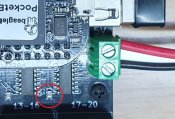
I have been a bit lax and haven't followed up on this thread for a bit. Do the screws on the terminal up tight with the wires in it. From the terminals to the capacitor circled in the pic below check for continuity. 1 side of the capacitor should be 0V and the other side 5V. After you have checked from the terminals measure from the power supply to the capacitor. If you have continuity everywhere that you should have then power up the power supply and check for 5V at the power supply, then the terminals and finally across the capacitor.
Attachments
janastas
Full time elf
- Joined
- Nov 30, 2020
- Messages
- 120
- Thread starter
- #27
I have been a bit lax and haven't followed up on this thread for a bit. Do the screws on the terminal up tight with the wires in it. From the terminals to the capacitor circled in the pic below check for continuity. 1 side of the capacitor should be 0V and the other side 5V. After you have checked from the terminals measure from the power supply to the capacitor. If you have continuity everywhere that you should have then power up the power supply and check for 5V at the power supply, then the terminals and finally across the capacitor.
Thanks Alan, I've sent you an email with some further details if you have time to read my sob story.
janastas
Full time elf
- Joined
- Nov 30, 2020
- Messages
- 120
- Thread starter
- #28
So a quick update on this thread.
The issue with the K40D-PB appears to have been a fused resistor which needed to be swapped out (troubleshooting courtesy of @AAH and @dkulp)
Thanks to @AAH for all his help over the weekend and early this week, he was kind enough to have a look at the board and make the repairs, test then send it back out my way.
I plugged it up last night and all is working as expected again and I'm a happy camper
Now to lock my self in the garage, build some more props and test them.