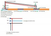
christinaadams said:This is a lot of great info in the forum and the lighting 101 manual. I just wanted to check when injecting the power from a single power supply if this diagram is correct for injecting power using the ws2811 strips and then soldering together the 2 and 3 core plugs? Is it fine to inject just after the 3 core male/female connection?
When running multiple +V and GND's out of the power supply to inject down the line how do you connect back into the power supply? Do you connect all the +V and GND's back to the same power supply terminal or split the power somehow once leaving the power supply?
Thanks!
What controller are you planning on using and are you planning on having seperate power supplies for each strip or one power supply for all. This will help me answer your question more directly.
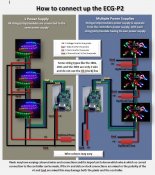
 each output of the ECG-P2 can run upto 4 universes, that means you could run upto 12 strips in series together and inject at certain places along the length. You could use multiple power supplies so you can help reduce any voltage drop over the length by placing those power supplies close to the injection points.