Power Injection at Multiple Points

BrianZ

Full time elf
Joined
Jan 2, 2021
Messages
101
Location
Miami, Fl.
I have a quick question...can I use one 14AWG cable and a 15a fuse block to power inject at multiple points? I’ll just be splicing into the cable at different inject points instead of running multiple PI cable from the block.
 

Srmorgan

Full time elf
Joined
Jan 26, 2020
Messages
100
That’s how I do my dense props and my front windows. Works great. Look up VCS 2020 Power Distro / Power Injection - Bill Porter he talks about it in his tutorial
 

TerryK

Retired Elf
Joined
Feb 9, 2020
Messages
655
Location
West Central Ohio
You can but one needs to sub-fuse. That is each splice into the prop needs to be fused down to protect the lower current device whether it is a string, strip, or flood, etc. The reason is if something would happen to cause the prop to absorb the entire 14 AWG fused 15 Amp load the wire and/or prop would burn.

Beyond that, one would then need to evaluate voltage drop relative to cable length and current draw as should be done with any power injection cable.
 

BrianZ

Full time elf
Joined
Jan 2, 2021
Messages
101
Location
Miami, Fl.
You can but one needs to sub-fuse. That is each splice into the prop needs to be fused down to protect the lower current device whether it is a string, strip, or flood, etc. The reason is if something would happen to cause the prop to absorb the entire 14 AWG fused 15 Amp load the wire and/or prop would burn.

Beyond that, one would then need to evaluate voltage drop relative to cable length and current draw as should be done with any power injection cable.
Do you recommend using multiple PI lines then?
 

TerryK

Retired Elf
Joined
Feb 9, 2020
Messages
655
Location
West Central Ohio
Do you recommend using multiple PI lines then?
For myself I have yet needed to but yes. If the voltage drop becomes too great or I would max the cable's amperage capacity I would add another power injection cable.

My design perspective presently is 14 AWG cable fused at 15 Amp power injection not through the controller but directly to the props with each injection point down fused to 5 Amp.
 

swampgator352

New elf
Joined
Mar 15, 2021
Messages
26
I have found the video posted earlier in this thread immensely helpful in understanding some of the conceptual ideas behind power injection. I'm getting a little bit hung-up, however, on the details surrounding wiring the harnesses into the pixel string. Does anyone have any labelled photos/diagrams that they would be able to share? Maybe an example with sub-fusing?

My understanding is that data does not need to be adjusted at all. Do I only need to make a break in my V+ line when injecting from a second PSU, or is it best to break the V+ at each power injection point? Then for the GND, do the GND wires from the pixel string both go in one end of the solder shrink tube while the GND from the power injection goes in the other end of the tube?
 

i13

Dedicated elf
Joined
Jul 5, 2013
Messages
1,172
For your question about breaking the V+ between each injection point versus each power supply, the answer is that it is essential to break it between each power supply. If you're fusing each injection point's positive separately, I would recommend breaking the positive between each injection point too. If there's a short, the fuses can share the higher load if you don't break the positive between them.

I think the answer to your question about the negatives and the solder shrink tube is yes. Are you referring to 30:00 in the video?

For a simple injection diagram, see https://auschristmaslighting.com/attachments/16394/
In this example, the fuses would go on the positive outputs of the power supplies. Nothing is powered through the controller. The power supplies can be different voltages too.

Once you're familiar with injection, you could try something insane like this https://auschristmaslighting.com/threads/10382/
 
Last edited:

swampgator352

New elf
Joined
Mar 15, 2021
Messages
26
Hi i13,

Yes, that is exactly the section I was talking about. Your clarification has been extremely helpful, thank you!
 

TerryK

Retired Elf
Joined
Feb 9, 2020
Messages
655
Location
West Central Ohio
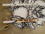
A rather poor and ugly example but...

This is a Gilbert Engineering rabbit I had out for Easter. Total pixels 268 and for better or worse, power injected at 4 points (beginning, 2 in the middle near pixels 90 & 180, and the end). Fed with a single power injection cable fused at 15 Amp near the supply, cable length about 28 feet as I recall. Data and V- only from the controller, a RPi B+ and Pi-Hat via Beldon 2 conductor 20AWG shielded (I think). Shield is not used, just trimmed back and covered with shrink.
Notes are in the graphic and to keep the insert size smaller resized to 1024x768 so the text suffered a bit. Fuses on the rabbit are 5 Amp. There may be an exception or two but from the connectors to pixels, wire lengths are no longer than about 20 to 25 inch. The tape (Yellow) on the PCV pipe hides most of the splices (fortunately).

1618976177440.png
 

swampgator352

New elf
Joined
Mar 15, 2021
Messages
26
This is very helpful, thank you so much for sharing! Does your white data wire originate from the Data In 22 AWG BTF Lighting Connector? I think I am seeing it break off to several different pixels, is that right? Why is that needed?

For the V+ wire, are the various in-line fuse legs spliced in by removing the insulation from the main wire from the Muyi connector then just soldered and heat shrinked?

Thanks so much for the patience with my novice questions!
 

TerryK

Retired Elf
Joined
Feb 9, 2020
Messages
655
Location
West Central Ohio
The "Data In" and "Data Out" (Pink Baggie) connectors each have a White 18 AWG silicone connected to them. As would be expected, the "Data In" White routes to the "Data In" of Pixel #1 and the "Data Out" White routes to the "Data Out" of the last pixel; #268 in this situation. They are difficult to follow due to the scrunched mess taped to the mounting tube. Resizing the graphic created some rather severe 'jaggies' which does not help either.

Yes, for the Black (V-) and Red (V+) from the Muyi, splices are added from the connector outward (one by one) using a rather old Craftsman stripping pliers to literally open an approximate 3/8 inch gap in the insulation. The insulation is not removed, just compressed and tugged a bit 'down-wire'. Sounds ugly doesn't it, but it works. :)

For the rabbit, the V- (Black) has 5 or 6 splices, 1 each for the data in and out and 4 more for the power injection. The V+ (Red) has 4 splices for the 4 power injection wires. In hindsight, the ATO/ATC fuse holders are huge and the wires are stiff. I probably should have utilized minis but so far their holders seem to be either 18 AWG or 14 AWG (gotta be a 16 AWG out there somewhere).
 
This thread is very old. An answer might not be needed anymore.
Top