Putting strobes together

toodle_pipsky

Minister of Silly Walks
Joined
May 9, 2010
Messages
334
Location
Toowoomba, Australia
Just looking @ these stobe PCBs and working out how it goes together! Most parts are obvious where they goe, just 3 questions:
1. Where does the LED go?
2. On the left side (looking at the board with U1 up the correct way) is that were header pins go to connect my PICkit 2 to program the pic? part 2 of that question is will I need to do that to each strobe (that is put header pins in and program each one)?
3. How do you wire up the connection to these - connection to strobe and connection to computer? Can you connect them in series or parrallel to run many from 1 channel?

Thanks for the help - they probably seem like obvious questions, but the wiki page doesn't have much info yet. :)
 
Work in progress

Have a look at the next couple of images
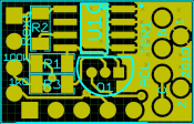
Top side of PCB

strobetop.png

Rext: the value of this resistor will based on the LED you will be using and sets the current.
2R for 1W
6R98 for 1/2W
33R for normal leds, sets current to 20mA

R1: 100K
R3: 1K

The 1W and 1/2W LED's connect to holes marked 1 and 2
1: Positive
2: Ground

U1: this is the NUD4001


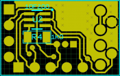
Now the bottom side of the PCB
strobebottom.png
U2: PIC 10F200
R4: 1K

The dot shows Pin1 of the PIC

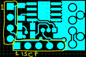
Now IO Connectors
strobeio.png

Connector on the LEFT is for Power and control signals
1: Vin, this MUST be 5v regulated when a PIC is used.
2: Ground.
3: Used only when no PIC installed... 5V will turn LED on
4: Used with PIC, connect to Ground to trigger PIC program

The one shown as ISCP is to connect your Pickit to.
Here's the circuit diagram
strobecircuit.png

Time to dig the video up to show that.
 
Thanks for writting it up. I was looking for a wiki on the other forum. I realize this is changing still and that there are many options going on right now.
 
Great timing Phil - Matt just sent off my parts/boards the other day so hopefully I'll be slapping a few of these together very soon. I'm planning to try my new SparkFun Controller/Oven (perhaps overkill but who cares!) to crank them out - maybe they'll make Halloween yet!

Thanks!
 
Just got my boards/parts today. Phil - just to clarify, can you flip the image showing the PIC placement (gold coloring) - the image you have is if viewed through the top layer versus if you phyically turn the board over. That would make it clearer to me anyway.

I would love to see the construction video regarding final portions of the build (installing the LED and inserting/waterproofing into the 'crystal' cap).

I'm also a little confused on a non-PIC situation and how the 4-pins are used. I was going to use my Ren48LSD to drive these which uses a DC configuration with flipped outputs (using transistors but similar to using ULN2803 like on Frank's Ren24LV) providing switched grounds (like DCSSRs as well). This seems to indicate you need switched +5v instead on pin 3 to trigger them (wrt to your comment "5v will turn LED ON")? Can I simply tie pin 1 and 3 together and switch the ground on pin 2?

If I use a PIC, then it seems to follow normal switched ground convention to pin 4.
 
budude said:
Just got my boards/parts today. Phil - just to clarify, can you flip the image showing the PIC placement (gold coloring) - the image you have is if viewed through the top layer versus if you phyically turn the board over. That would make it clearer to me anyway.

I would love to see the construction video regarding final portions of the build (installing the LED and inserting/waterproofing into the 'crystal' cap).

I'm also a little confused on a non-PIC situation and how the 4-pins are used. I was going to use my Ren48LSD to drive these which uses a DC configuration with flipped outputs (using transistors but similar to using ULN2803 like on Frank's Ren24LV) providing switched grounds (like DCSSRs as well). This seems to indicate you need switched +5v instead on pin 3 to trigger them (wrt to your comment "5v will turn LED ON")? Can I simply tie pin 1 and 3 together and switch the ground on pin 2?

If I use a PIC, then it seems to follow normal switched ground convention to pin 4.

Hey Phil - any update on this? There are many folks now with a pile of parts and not 100% sure how to build them or how to configure/use them.

edit - I decided to build one up tonight and I think I have it figured out - it looks great!. I'm still a bit fuzzy on how the trigger will be sent if using the PIC version. It says to supply a ground but not sure how that would be supplied from a DC based controller unless you're also supplying the power to it?

Thanks!
Brian
 
Just spotted your instructions on DIYC budude - excellent. Also thanks Phil for your description here. Will give it a bash tomorrow. Thanks again guys
 
Hi. I'm trying to strobes working using 1w leds. I have used 2r2 resister in Rext,100k in r1 and r4 and 1k in r3 as well as the nud and Q1 and LED to pins 1 and 2. if i put power to pin 2 and 3 should i see the light??
 
Does option one of this build only require R2 and the NUD with power to pins 2(com) and 3(5v+)
 
Steve said:
Hi. I'm trying to strobes working using 1w leds. I have used 2r2 resister in Rext,100k in r1 and r4 and 1k in r3 as well as the nud and Q1 and LED to pins 1 and 2. if i put power to pin 2 and 3 should i see the light??

Only R1 is 100k, R3 and R4 are both 1K and R2/Rext should be 2.2ohm as you indicated. Not sure if it's correct, but I basically built the non-PIC version exactly the same as the PIC version - except with no PIC - with all the resistors and transistor. To run it, I ran a jumper from pin 3 of the control interface to pin 2 of the ICSP interface (which is +5v). Then you just run +5v/Gnd to pins 1/2 respectively of the control interface. This basically makes CC LED and you drive it with a DC controller of your choice.

As for the PIC version, I will be jumpering pins 2 and 4 of the control interface - which is pin 4 to ground and again running pins 1/2 to your DC controller. This will produce a random effect as well. I did not think it was convenient to run 3 wires to each strobe (IMHO).

I think there is something missing from the instructions to make the simplest circuit because the NUD will not get ground w/o the transistor. My guess is only using the Rext resistor and jumpering the C to E junction of the transistor to bypass it. To be honest though, I have all the parts so I'll just build them with all the components.
 
Thanks Brian. I did see your posts and pictures on DIYC. I too have all the parts.I think i will just have to wait till someone brings out proper instructions on the build before i waste too many more.
 
Steve said:
Thanks Brian. I did see your posts and pictures on DIYC. I too have all the parts.I think i will just have to wait till someone brings out proper instructions on the build before i waste too many more.

Well - I knew I would not be using the parts for anything else and I figured all I would need to do in the future is just add the PICs and then it would be a complete strobe. The two versions I built work as random fire mode or basic CC mode by just applying 5v/Gnd.
 
Sorry if I sound a little dumb here . . . I've got all the resistors except for 6r98 ones, I do have ones marked 7r15. Did I miss something that these are substitutes? I'm using .5w leds. Thanks for the help guys.
 
I'd say so Ingrid. Those values are only a few % different, so no cause for concern. The 7R15 will lower the LED current just a smidge - not even a visible difference.
 
Back
Top