Rainbow Wall Wash - Current issue

budude said:
I guess I need to change my userid to "Doubting Thomas"... ;)

I'm guessing that the same Piranha LEDs are used for the RFs as the RWRs and they are rated at 30mA so I find this hard to believe they are running at 170mA? It almost sounds you are an entire magnitude off (i.e. digit needs to move over one to .035A or 35mA/2) and perhaps they are 20mA LEDs so they are getting 17mA each which would be reasonable. Greg mentioned using 20mA LEDs at one point and 30mA later on but not sure if it applies to these...

Here is a picture of the rainbow wall runner at 12vdc drawing 0.38 amps after running for 15 minutes with the bottom of the board resting on the chair.
 

Attachments

  • PICT3439.png
    PICT3439.png
    1.4 MB · Views: 66
In the picture it looks like the yellow meter is selected to the 20V (or hfe) range. It is selected to the 10A position isn't it?
 
Yes it is selected to 10 amp range, i thought the same thing after looking at the photo but its due to the angle the picture is taken at.
 
OK - I know the "picture is a thousand words" line - - but - - can you measure the drop resistor value (either/both) and the voltage across it - I = V / R so this will put this to bed once and for all. I'm still struggling with 30mA LEDs running at 185mA... I assume in your picture that your yellow meter is in series with the supply and not across it?
 
If you look closely at the picture you will actually be able to see that the yellow meter is connected in series.
The drop down resistor is 2 ohms @ 5% (brown, black, gold, gold) and this was also measured as being 1.95 ohms. (The V2 RWR manual actually specifies a 1 Ohm resistor but I was supplied with a 2 Ohm resistor)
I expect the calcs will be close to the measure forward voltage which i will check later this evening.
 
Ok the measured voltage through the resistor is 11.76VDC, the supply CAT 5 cable has a 0.05VDC voltage drop. The power supply has an output of 12VDC so the voltage drop across the resistor is 0.19 Volts
 
Eddy,

Can you please verify that you got a 2ohm resistor? The bands you specified are for a 1 ohm resistor, which is what should be on the wall runners. I had to think about it and verified it here:

http://www.sizes.com/materls/resistorcolor.htm

I don't think you should have gotten a 2 ohm, but stranger things have happened. Just make sure that you did and I will send you replacements. BROWN, BLACK, GOLD, GOLD, however = 1 ohm @ +/-5%

Greg
 
He indicated he measured the resistor at 1.95ohms - - but surely it should not be less? Going from 2 to 1 ohm would only double the current!

Eddy - from your post it sounded like you deduced the voltage across the resistor instead of measuring it - is that the case? Can you just measure the voltage directly across the resistor?
 
Sorry i made a mistake it is definetly a 2 ohm resistor (in measured value) and is a red band, i was going off memory when i wrote down the colors. It was definetly measured as a 2 ohm resistor and if memory serves me right (it didnt before) it would be a red band and not brown. Thanks for highlighting my mistake.
Just to confirm i will post up a picture tonight if it in fact has the 2 ohm resistor. I will also reconfirm the voltage drop across the resistor, but the figures supplied were measured. I prefer the 2 ohm resistor rather than a 1 ohm resistor so i wouldnt require a replacement resistor either way.
 
ponddude said:
Eddy,

Can you please verify that you got a 2ohm resistor? The bands you specified are for a 1 ohm resistor, which is what should be on the wall runners. I had to think about it and verified it here:

http://www.sizes.com/materls/resistorcolor.htm

I don't think you should have gotten a 2 ohm, but stranger things have happened. Just make sure that you did and I will send you replacements. BROWN, BLACK, GOLD, GOLD, however = 1 ohm @ +/-5%

Greg

Greg

This is getting ridiculous, 350mA of current through two parallel connected sets of five Red 30mA series connected LED's is just plain WRONG, the total current drawn by the two series strings should be 60mA and this certainly requires a resistor in at least Eddie's case of GREATER than TWO Ohms.... NOT a reduction back the the ONE Ohm you are promoting.

The current version of this design is inherently flawed with the use of five series connected RED LED's.

Phil
 
AussiePhil said:
ponddude said:
Eddy,

Can you please verify that you got a 2ohm resistor? The bands you specified are for a 1 ohm resistor, which is what should be on the wall runners. I had to think about it and verified it here:

http://www.sizes.com/materls/resistorcolor.htm

I don't think you should have gotten a 2 ohm, but stranger things have happened. Just make sure that you did and I will send you replacements. BROWN, BLACK, GOLD, GOLD, however = 1 ohm @ +/-5%

Greg

Greg

This is getting ridiculous, 350mA of current through two parallel connected sets of five Red 30mA series connected LED's is just plain WRONG, the total current drawn by the two series strings should be 60mA and this certainly requires a resistor in at least Eddie's case of GREATER than TWO Ohms.... NOT a reduction back the the ONE Ohm you are promoting.

The current version of this design is inherently flawed with the use of five series connected RED LED's.

Phil

Phil

Just out of curiousity,
would you please share your calculations that proves why the design is "just plain wrong" and "inherently flawed"??

Thanks
RS
 
It's really quite simple. The Vf (forward voltage) of an LED is not perfectly constant, but instead varies with temperature and the drive current. It can also vary from batch to batch.

Say you have 5 x LEDs in series, resulting in a total Vf of 11V (5 x 2.2V). To use this on a 12V power supply, you need to drop 1V across your series resistor. Given a drive current of 30mA, the would mean a 33 Ohm resistor would be required. (1V / 33 Ohms = 0.03A)

Now, what happens when the Vf is 2.1V instead? With the same 12V source, the resistor now needs to drop 1.5V, but this will result is in a 50% current increase (to 45mA). The same situation also happens if the power supply increases to 12.5V even with Vf staying the same. (1.5V / 33 Ohms = 0.045A)

But it gets even worse. With lower value resistors, any change in either Vf or the supply voltage makes for a huge variation in the LED drive current. You can imagine what happens when you get into the sub 10 Ohms area - total chaos!

What's the solution? To maintain the LED drive current within a reasonable tolerance, the voltage dropped across the series resistor needs to be large compared to the sum of the variation if each LED's Vf. Simply using 4 LEDs would change the total Vf to 8.8V (4x 2.2V) and have the resistor dropping 3.2V instead.

By doing that, any variations in Vf or power supply voltage have only a minor impact on the LED drive current. The larger resistor value (say 106 Ohms) would still result in 30mA current with a 12V supply (3.2V / 106 Ohms = 30mA). If the LED Vf changes to 2.1V, the current would only increase to 34mA (3.6V / 106 Ohms = 34mA) which is only a 10% increase, not 45mA (50% increase) like the first example.

I hope that clears up why using very low value series resistors in LED applications is a really bad idea.
 
Very well explained David. This is why the rainbow floods are better as they use 3 LEDs in series with a high resistor value as apposed to 5 LEDs with a low resistor value for the red on the rainbow wall washer.
 
android said:
AussiePhil said:
ponddude said:
Eddy,

Can you please verify that you got a 2ohm resistor? The bands you specified are for a 1 ohm resistor, which is what should be on the wall runners. I had to think about it and verified it here:

http://www.sizes.com/materls/resistorcolor.htm

I don't think you should have gotten a 2 ohm, but stranger things have happened. Just make sure that you did and I will send you replacements. BROWN, BLACK, GOLD, GOLD, however = 1 ohm @ +/-5%

Greg

Greg

This is getting ridiculous, 350mA of current through two parallel connected sets of five Red 30mA series connected LED's is just plain WRONG, the total current drawn by the two series strings should be 60mA and this certainly requires a resistor in at least Eddie's case of GREATER than TWO Ohms.... NOT a reduction back the the ONE Ohm you are promoting.

The current version of this design is inherently flawed with the use of five series connected RED LED's.

Phil

Phil

Just out of curiousity,
would you please share your calculations that proves why the design is "just plain wrong" and "inherently flawed"??

Thanks
RS
RS

David_AVD has already explained it really well.

The design is inherently flawed by using a quantity of series connected LED's that have a combined nominal Forward voltage drop approaching or equaling the supply voltage AND by supplying a current limit resistor of a single fixed value.

ALL LED's will have variations in Vf and a range of data sheets for Piranha LED's show the red ones to have a range of 2.2 to 2.4v for one quality BIN.
Due to the variation that can be experienced the current limit resistor in this design would need to the measured for EVERY set of red LED's, only by measuring can you ensure the correct current of 30mA.

As this design is aimed at the DIY market with absolutely no information on how to determine the correct resistor values there can be little doubt that it is inherently flawed and highly disappointing to see that this is not recognised by the designer.

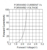
This image is taken straight from a piranha LED data sheet and clearly shows how current varies greatly with small variations with Vf
Vfgraph.png

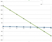
This image is a direct analysis of the RWR Red LED setup at 12V and the recommended one ohm resistor.
The green line shows the current in mA for different LED Vf figures.
A 0.1v variation on the low side would see current increasing to 500mA and this is shown in the practical tests being done.
Capture.png

Phil
 
Back
Top