Removing MFC on Kmart LEDs

starburster81

New elf
Joined
Oct 21, 2014
Messages
16
Location
Marsden
Hi guys,
First time poster, so please forgive me if I screw up with the rules!
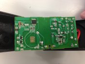
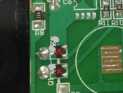
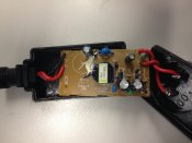
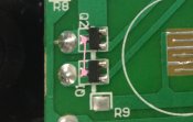
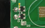
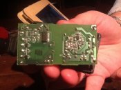
I have a heap of Kmart LED lights with 8 multifunction controllers. I'm a teacher and work with a few ex-electricians who are happy to have a play with the controllers for me. I want the lights to be steady on and I know it's a matter of soldering the circuit board but I had a look at the wiki and none of the circuits pictured match the ones in the Kmart lights. Has anyone done the kmart LEDs before?
They are the transformers that plug directly into the powerpoint, so the controller and powerpoint are all the same unit.
Anyone have any ideas?
Cheers!
B
 

David_AVD

Grandpa Elf
Community project designer
Generous elf
Joined
Jun 12, 2010
Messages
4,681
Location
Victoria Point (Brisbane)
If you post pictures of the PCB from and back I might be able to help.

You can't dim those PSU/MFC units though. I'm not sure I'd even run them from a 240V controller.
 

starburster81

New elf
Joined
Oct 21, 2014
Messages
16
Location
Marsden
Ok, here is the circuit board. I know the right hand side is the 240V side, and I know the points I need to modify are on the left - I just don't know which ones.
I don't want to dim them, I just want the lights to remain steady on so I don't have to press buttons for an hour each night. Thanks David, any help is appreciated! :D
 

Attachments

  • IMG_2935.JPG
    IMG_2935.JPG
    1.6 MB · Views: 50

benzor84

Apprentice elf
Joined
Feb 28, 2014
Messages
53
Location
Sydney
This is how i would do it.
You wont need to remove the fets but they wont be used any more so don't worry about hurting them.
I would scrape of a small patch of solder mask on the source side and just make a solder bridge to the load side.
make sure not to short out the gate pads (bottom right on each fet)
 

Attachments

  • mfc.jpg
    mfc.jpg
    195.6 KB · Views: 43

starburster81

New elf
Joined
Oct 21, 2014
Messages
16
Location
Marsden
This is the other side. Same deal, the 240V is on the right hand side.
 

Attachments

  • photo.JPG
    photo.JPG
    2 MB · Views: 34

starburster81

New elf
Joined
Oct 21, 2014
Messages
16
Location
Marsden
Ok thanks. That's pretty much what I and the engineering teacher had in mind. Just to clarify and make it easier for both of us:
Source side is the top, Q2? Run a solder bridge to the load side, next to Q1.
That would be a line running from the two squares on the left of the FET.
Check out the picture and let me know. I know I sound like a total newbie, and I am really. But thank you guys so much for your help :)
 

Attachments

  • mfc.jpg
    mfc.jpg
    128.4 KB · Views: 33

David_AVD

Grandpa Elf
Community project designer
Generous elf
Joined
Jun 12, 2010
Messages
4,681
Location
Victoria Point (Brisbane)
Both of the pads on the left (pink in your picture) need to link to the fat trace above them where it says Q2. That's the PSU -ve line.
 

starburster81

New elf
Joined
Oct 21, 2014
Messages
16
Location
Marsden
David_AVD said:
Both of the pads on the left (pink in your picture) need to link to the fat trace above them where it says Q2. That's the PSU -ve line.
Ok, like this then? Just getting it straight in my head :)
 

Attachments

  • mfc.jpg
    mfc.jpg
    129 KB · Views: 38

benzor84

Apprentice elf
Joined
Feb 28, 2014
Messages
53
Location
Sydney
yep.
Just use a exacto knife to scrape back the solder mask so you have nice shiny copper to solder to.
 

starburster81

New elf
Joined
Oct 21, 2014
Messages
16
Location
Marsden
This is the other circuit board. Just wasn't sure where the -ve was :-\
 

Attachments

  • image.jpg
    image.jpg
    221.8 KB · Views: 27
Top