Restrict DC-DC buck to 5v

deblen

Full time elf
Joined
Mar 20, 2011
Messages
146
HI,

I have Buck converters which output to 5 volt.
Is their a way I can restrict the out put to 5 volt between the buck and the pixel strip, by way of a fuse or some type of resistor.

I have heard that when or if the buck fails, the voltage increases, resulting to damage to the pixels

Thanks in advance

Deblen
 

AAH

I love blinky lights :)
Community project designer
Joined
Dec 27, 2010
Messages
4,188
Location
Eaglehawk
The usual way is to use a crowbar circuit set to maybe 5.2V between the buck and the panels. What it does it detects the higher than desired voltage and effectively shorts to ground blowing the fuse. It doesn't look like there's anything on Aliexpress or Ebay off the shelf. The alternate is to use something like a overvoltage relay something like https://www.ebay.com.au/itm/1pc-Vol...505245?hash=item25f5bba49d:g:R50AAOSwpDdVbC8c . There will always be a delay and the relay needs to be sized according to the load. With P10's pulling somewhere in the range of 2-3A per panel the linked 1 is essentially useless for more than 4 panels. You could use the module to control external relay/s but that also adds an additional delay of 10's of milliseconds which may or may not matter.
 

deblen

Full time elf
Joined
Mar 20, 2011
Messages
146
Hi Allan,
Thanks for the feedback, looks like it is not easy as I thought it would be.

When you talk about a crow bar circuit, would this be a way to go, if so what would you need to setup.

Or would you be able to design a cost effective board.

I am wanting to use the bucks on strips, as I purchased 15 of them last year.

Deblen
 

AAH

I love blinky lights :)
Community project designer
Joined
Dec 27, 2010
Messages
4,188
Location
Eaglehawk
David and I have just been talking crowbar circuits. I have no interest in building them myself. I did think a couple of years ago of implementing them into an Octoscrolla board but decided against it. There is probably options on Feebay or Aliexpress that would do the job or do it with very little modification.
 

David_AVD

Grandpa Elf
Community project designer
Generous elf
Joined
Jun 12, 2010
Messages
4,681
Location
Victoria Point (Brisbane)
I've been thinking about the crowbar circuit a bit more.

What would be the maximum load current you'd want to protect?

This current determines the fuse size and rating of the TRIAC that blows the fuse in the fault condition.
 

David_AVD

Grandpa Elf
Community project designer
Generous elf
Joined
Jun 12, 2010
Messages
4,681
Location
Victoria Point (Brisbane)
Doing one that can handle a fair chunk of fault current will not be a $5 board.

I'll look into what can be done and the likely cost. Even a $20 board would be better than $200 or more worth of roasted LED panels.
 

OzAz

Senior elf
Global moderator
Joined
Dec 29, 2015
Messages
997
Location
Newcastle
It might depend on cost of boards.
If I was to use them, if they were cheap enough, I'd have 1 per prop or group of props.
So maybe several low current 1-5A ones rather than 1 high current (15A + ) one.

For instance, I was thinking of using one for each of my halloween props which draw 1-3A. These props cost from $45 up, so a $5-10 board is worth it to protect each one.
 

darylc

404 darylc not found
Joined
Dec 8, 2012
Messages
1,146
Good point, I always break out that 25A into 3-5 smaller feeds, so n x lower current boards may work
 

deblen

Full time elf
Joined
Mar 20, 2011
Messages
146
Hi David,

Would it be possible to investigate the cost of both suggestions as indicated by DarylC and OzAZ.
Thaanks for looking into a solution for this.
I think the cost would be negligible, if one had to pay replacement, also another way of protecting our investment.

Deblen
 

Barnabybear

New elf
Joined
Mar 30, 2012
Messages
42
Location
UK
Hi, whilst not an elegant solution, could 8 off 1N400x diodes be linked in series and placed across the 5V just after the buck converter/fuse, Anode to 5V and Cathode to Ground. These wouldn’t conduct until the forward voltage had been reached, somewhere just under 0.7V or 5.6V for 8 off in series, I suspect testing would show this to be slightly lower. They are rated up to 30A for bursts which should be plenty to blow a 5A fuse and are cheap as chips. The exact rating at which the clamping would take place depends on the tolerances of the 1N400x and may in reality need 9 diodes or a schottky for fine tuning; all this should be easy enough to test with a current limited bench power supply.
 

AAH

I love blinky lights :)
Community project designer
Joined
Dec 27, 2010
Messages
4,188
Location
Eaglehawk
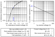
Using diode won't work. The "on" voltage of diode is highly dependent on the current. A 1n4004 at zero current will have a forward voltage of a nominal 0.7V. 7 in series will start conducting when the voltage is "about" 4.9V. Depending on the type of overload the diode may never conduct enough to blow
a fuse.
1N004.png
 

Barnabybear

New elf
Joined
Mar 30, 2012
Messages
42
Location
UK
Hi, agreed from the data sheet it looks like the 1N series of diodes wouldn’t provide suitable voltage over protection. I’ll follow with interest to see where this ends up.
 
Top