Steve22537
Full time elf
I'm in the process of developing a RGBW+Strobe / 6 Channel DMX Controller with P-DMX. The original concept was based on the JEC and WJohn designs.
The idea was to have a small device that could be attached to each Mini Tree that supported DMX and had minimal cabling, hence a single CAT5 cable can be run between each tree suppling power and data. The Mini Trees have 5 different coloured strings, each being 5m long and 5 ACL Strobes.
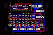
The device can be mounted in a 82 x 54mm Jiffy Case, and has the option to enable / disable P-DMX and allow the user to configure it as a RGBW+Strobe Controller or 6 Channel Controller with the addition of a few components. The device has Power In / Out so the Power can be daisy chained between devices if the user doesn't want to use P-DMX. It has been designed to run at +24v and is internally fused to protect the cabling and other devices down the line. The final design still needs a little bit of tinkering but its not that far away and final costings haven't been finalised. Part of the design scope was to make it so that the components could be sourced from your local Jaycar or Altronics at minimal cost.
There are a few changes to the board layout and the circuit layout that still need to be done, but this is the start.
EDIT: The PCB has had a few minor changes.
The idea was to have a small device that could be attached to each Mini Tree that supported DMX and had minimal cabling, hence a single CAT5 cable can be run between each tree suppling power and data. The Mini Trees have 5 different coloured strings, each being 5m long and 5 ACL Strobes.
The device can be mounted in a 82 x 54mm Jiffy Case, and has the option to enable / disable P-DMX and allow the user to configure it as a RGBW+Strobe Controller or 6 Channel Controller with the addition of a few components. The device has Power In / Out so the Power can be daisy chained between devices if the user doesn't want to use P-DMX. It has been designed to run at +24v and is internally fused to protect the cabling and other devices down the line. The final design still needs a little bit of tinkering but its not that far away and final costings haven't been finalised. Part of the design scope was to make it so that the components could be sourced from your local Jaycar or Altronics at minimal cost.
There are a few changes to the board layout and the circuit layout that still need to be done, but this is the start.
EDIT: The PCB has had a few minor changes.