HertzSwift
Apprentice elf
Hi everyone, I've been sequencing shows for a couple of years now, I officially call it a hobby now! My shows have consisted of rope light frames, fairy light string lights and dump RBG pieces. This year I would like to introduce pixels into my setup, and my first project will be a mega tree.
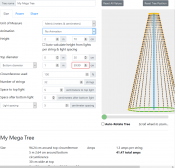
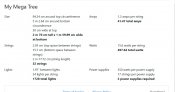
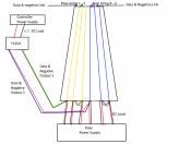
My questions is about the Falcon F16V3 pixel controller and how to wire a mega tree to it. I've attached an image of the rough dimensions of the mega tree I plan to make.
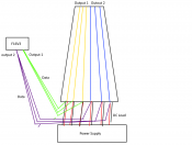
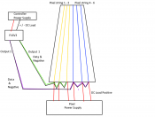
So my understanding is the F16V3 has 16 outputs, and each output can control 1024 pixels, limited by 5 amp per output. So power injection would be the only way to get to the 1024 limit correct? Could I power this tree via the controller without the need for power injection?
How many pixel strings can I wire up to each channel? The mega tree calculator says each string, which consists of 54 x 12 VDC pixels, and it draws 1.3amps per string, so each channel could drive 3 strings? This does not exceed the 5A per output. So this would use a total of 11 channels
Do you wire in channel 1 first, followed by channel 2 etc, or does it not matter which pixel gets wired into which channel and its all configured via the software?
Am I on the right track here? Any help apprecaited
My questions is about the Falcon F16V3 pixel controller and how to wire a mega tree to it. I've attached an image of the rough dimensions of the mega tree I plan to make.
So my understanding is the F16V3 has 16 outputs, and each output can control 1024 pixels, limited by 5 amp per output. So power injection would be the only way to get to the 1024 limit correct? Could I power this tree via the controller without the need for power injection?
How many pixel strings can I wire up to each channel? The mega tree calculator says each string, which consists of 54 x 12 VDC pixels, and it draws 1.3amps per string, so each channel could drive 3 strings? This does not exceed the 5A per output. So this would use a total of 11 channels
Do you wire in channel 1 first, followed by channel 2 etc, or does it not matter which pixel gets wired into which channel and its all configured via the software?
Am I on the right track here? Any help apprecaited