Wiring two power supplies to 2 banks on 1 controller

nmiller0113

New elf
Joined
Oct 29, 2012
Messages
33
Location
California
I've read through the AUSChristmas 101 manual and I see that it mentions sharing the DC ground when using two power supplies. Is this the case even when I'm connecting to a controller like a Pixlite 16 on two different banks? For reference I'm using two of these http://www.holidaycoro.com/350w-Dual-Output-Power-Supply-p/49.htm?CartID=14. Do I still need to share the ground or V- between the two? I understand that if I'm doing any injecting from either of these power supplies as well that I should be using the same one that is powering the bank the string is originating from.


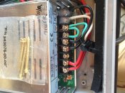
I'm also a bit confused on one more part. I know there are 3 conductors on the AC side - Neutral, Line and Ground. On the DC side there is only V+ and V-. I see in the 101 manual that the V- is referred to as ground. Are V- and Ground the same? How does Neutral relate to these? Or rather how do V-, Neutral and Ground all relate? Sorry for the million questions :) I've also attached a photo of a power supply I purchased awhile back, I forgot from who, but it came with a Loop between the AC ground and the V- side of the power supply. Do I need to be doing this as well? I couldn't find any reference to it anywhere in the 101 manual or online. Thanks for your help!
 

Attachments

  • IMG_0452.JPG
    IMG_0452.JPG
    788.6 KB · Views: 88

BundyRoy

Dedicated elf
Joined
Apr 9, 2014
Messages
1,026
There is no need to connect the v- between the two banks on the controller. (see David's post, they are already connected within the controller).

As for the AC and DC side of things. I always thought it should be "never the two shall meet". I would be removing that link from the v- to the ground. Will be interested to hear from others if having that linked could result in damage to the PSU.
 

logandc99

Dedicated elf
Joined
Jul 13, 2012
Messages
1,153
Also can't see the need for that loop wire and as Bundy said, would be concerned about causing damage. I have multiple power supply setups with no such loop. Maybe the electricians in the group can comment regarding the potential for damage or not.
 

nmiller0113

New elf
Joined
Oct 29, 2012
Messages
33
Location
California
I looked around and found that it was the one I purchased before I knew anything about this stuff and needed something pre-built for me. I bought a PS1 from Jim at SanDevices. This is how it came wired from him. I emailed Jim as well to see if he knew why he did it and whether it was a best practice or what. Thanks for the quick responses everyone...I look forward to hearing more from all of you. Especially more info about the loop as well as the how V-, Neutral and Ground all relate. Thanks again!
 

plasmadrive

Full time elf
Joined
Jan 12, 2012
Messages
248
Location
Elk Grove, CA
First off, you should tie the V- of the two supplies together. That creates a reference for all signal and DC power. They should remain as close to the same as possible. If you have one float from the other except as connected by your controller, should there be a current differential it could work it's way thru the PCB and that might be smoke time. Tie em together and with full side wire.

As for the wives tail about never the two shall meet, that is not true. However, some supplies don't like it for noise reasons. Others don't like it because they are not isolated and grounding the V- might do bad things.. but I have yet to see that happen for that reason. Many supplies are made so you can ground the V- and that sometimes helps with noise. IN the USA I believe I remember a code section in the NEC that requires it if the primary is over 150v. I haven't read it in a long time.. but I know it is there in some fashion. Maybe a current electrical guy can chime in on this one.

You asked what the relationship is between Neutral and Ground. Neutral is grounded at a newly derived source. ie... your meter main on your house, the secondary of a control transformer. There are cases where the neutral is floating but those are not common. Code also say you never ground neutral other then at that derived source. So is you have a sub panel down stream of your meter main, you do not tie ground and neutral together. One is for power imbalance return and the other is for safety.
 

David_AVD

Grandpa Elf
Community project designer
Generous elf
Joined
Jun 12, 2010
Messages
4,681
Location
Victoria Point (Brisbane)
If you have two power supplies feeding one controller (on different banks), do not join the negative terminals at the power supply end. The will be joined at the controller (internally) and that is the correct way to do it.

By joining the negative terminals at the power supply end, you are potentially modulating the negative line of one power supply with the load current of the other. This can lead to instability especially in systems with PWM (dimmed) loads.
 

Habbosrus

Back again
Joined
Dec 5, 2012
Messages
758
Location
Swansea, NSW
David_AVD said:
If you have two power supplies feeding one controller (on different banks), do not join the negative terminals at the power supply end. The will be joined at the controller (internally) and that is the correct way to do it.

By joining the negative terminals at the power supply end, you are potentially modulating the negative line of one power supply with the load current of the other. This can lead to instability especially in systems with PWM (dimmed) loads.
I have 2 x 350w 5v power supplies running my matrix. I am using 1 x E6804. PS1 supplies power for controller and outputs 1 & 2. PS2 supplies power to outputs 3 & 4 (I didn't connect v+ at controller for these 2). I have connected the v- between both power supplies. Is this incorrect? (just when I thought I was starting to understand :eek: [SIZE=78%])[/SIZE]
 

David_AVD

Grandpa Elf
Community project designer
Generous elf
Joined
Jun 12, 2010
Messages
4,681
Location
Victoria Point (Brisbane)
Habbosrus said:
I have 2 x 350w 5v power supplies running my matrix. I am using 1 x E6804. PS1 supplies power for controller and outputs 1 & 2. PS2 supplies power to outputs 3 & 4 (I didn't connect v+ at controller for these 2). I have connected the v- between both power supplies. Is this incorrect? (just when I thought I was starting to understand :eek: )

I'd really need to see a diagram of exactly how that's hooked up to comment further.
 

Habbosrus

Back again
Joined
Dec 5, 2012
Messages
758
Location
Swansea, NSW
David_AVD said:
Habbosrus said:
I have 2 x 350w 5v power supplies running my matrix. I am using 1 x E6804. PS1 supplies power for controller and outputs 1 & 2. PS2 supplies power to outputs 3 & 4 (I didn't connect v+ at controller for these 2). I have connected the v- between both power supplies. Is this incorrect? (just when I thought I was starting to understand :eek: )

I'd really need to see a diagram of exactly how that's hooked up to comment further.
Will take a photo and upload this evening. I did some testing last night and all seemed good. However, I want to make sure I have it right. Smoke looks ok when accompanied by fireworks, but not from my new matrix :D
 

BundyRoy

Dedicated elf
Joined
Apr 9, 2014
Messages
1,026
Steve, I think my setup is like yours. I have a controller that is powered by one PSU and some of the outputs are also powered off this controller with the same PSU.

Then I have my matrix that is powered by a separate PSU but controlled by the same controller. On these outputs there is only the data and V- coming from the controller to the matrix lights. I have disconnected the V+ at the controller so there is no chance the two PSU can be linked. I have then run the power (v+ and v-) from the second PSU to the lights on the matrix. Both the v- (1 from second PSU and one from controller) are joined at the lights as I thought it was best to have them joined as close to the lights as possible.

I do not have the v- joined between the two PSU's at the PSU's.
 

plasmadrive

Full time elf
Joined
Jan 12, 2012
Messages
248
Location
Elk Grove, CA
David_AVD said:
If you have two power supplies feeding one controller (on different banks), do not join the negative terminals at the power supply end. The will be joined at the controller (internally) and that is the correct way to do it.

By joining the negative terminals at the power supply end, you are potentially modulating the negative line of one power supply with the load current of the other. This can lead to instability especially in systems with PWM (dimmed) loads.

I disagree with you on this one.... unless the supplies are a good distance from the controller wire wise.. But hey.. what do I know? :-X

Edit: This does not make me correct.. it just means I disagree. My comments are with certain criteria in my head for the setup. Other situations and setups may be different.

When they are all together in the same enclosure then I believe I am correct about the V- ties.. However, if the supplies are a distance apart (which doesn't seem to fit the OP question) I agree 100% with you. I have at least one setup like that. Two supplies about 40' apart wire wise and the V- sides are tied to their respective loads with a wire for reference going back to the single controller..
 

nmiller0113

New elf
Joined
Oct 29, 2012
Messages
33
Location
California
According to AUS101 If you're using two power supplies to inject power you're bridging the -V, so what is the difference if you're doing it somewhere down a strip or directly between the two. As an example Let's say I use the same power supply for the controller which also powers the outputs. Then down the line I use a different power supply and tap the -V into the current -V but don't continue the +V with the new +V. I don't see the difference from bridging the two directly or down the line.

Two banks on the pixlite 16, which is the controller I'm using, also allows for two different voltages like 5v and 12v simultaneously. Would you still tie the -V together then?


Since Fasteddy wrote the 101 manual, I'm wondering what his thoughts are here? Thanks again everyone for your input!
 

nmiller0113

New elf
Joined
Oct 29, 2012
Messages
33
Location
California
I was just speaking to Devo in chat since he's part of Advatek lighting who makes the Pixlite 16 which I'm connecting these power supplies to. His response was:

“Ok, firstly it won't really matter about where you connect the grounds. They are both joined on the PCB anyhow, so connecting them at the PSU won't change much. It will work either way, but if I had a preference I would just let them be connected at the controller rather than at the supply as that will keep any potential small ground differential voltages to a minimum.

Secondly, don't ever connect your AC ground the DC V- output. They are very different in that AC ground connects to the literal ground somewhere for earthing safety, and DC "ground" on the PSU output is for a 0v reference point for the DC circuitry.In short, Ac ground is always kept separate from DC ground.”

So it looks like the controller does handle it though we could do it direct as well...either way...but he mentioned the perferred method is allowing the controller to. He also disagreed and warned against the AC ground to DC -V loop. I'm still curious why the SanDevices PS1 came that way. I'm waiting to hear back from Jim and when I find out I'll let everyone know what he says. Either way...it worked for two years that way, though I'm going to remove it now :)
 

BundyRoy

Dedicated elf
Joined
Apr 9, 2014
Messages
1,026
I notice that there is silastic on the live and neutral wires on the PSU. I gather this is to give a bit of extra protection against getting zapped by inadvertently touching both at once with your fingers. I've been a bit worried about the potential for getting electric shocks. Mainly by children. The options I can see for protection are:

1) Silicon
2) lock on controller enclosure

Is there any other options that give a bit of protection against electric shock on these PSU's where the terminals are exposed.

Sorry for the hijack, but thought it was sort of relevant as it relates to the picture.
 

miked

New elf
Joined
Aug 11, 2011
Messages
40
Location
Ipswich Qld
Have a question about running different voltages into the one controller and thought I would post here as it is along similar lines. Last year I did a half tree with LED light strings and this year I will be doing a full tree again with LED strings. To save channels and costs of controllers I want to mirror the half tree so want to plug 2 sets of strings into the one channel on the board. I have 20 strings each of R G B W in the half tree =80 channels . The full tree will be 160 channels, so that I want to plug R1 and R21 for example into the same channel on the board ( I am using Ray's 27 channel DMX boards).Unfortunately with time I now have a situation where the first half of the tree is 30V DC run Big W lights and the other half 24 volt lights ( Big W aren't bringing out red and green!!!!) . Not an ideal situation but I have to run with this year. Please see attached diagrams- sorry they are a bit rough. I have run dual voltages as per diag 1 for the last two years with no issues and I am assuming the diagrams are the same scenario- but one should never assume!!
Appreciate any input.
Regards
miked
 

Attachments

  • Dual Voltage Set Up.docx
    20.2 KB · Views: 33
Top