jediknight2
Full time elf
Just want to verify what I am doing here. These are 12v pixels and I am using an ECG-P2. Here is a photo of the Pback of my pixel.

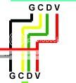
In the photo, you can see I have a four wire setup. Black is Postivie, Red is Clock, Green is Data and Blue is Negative ...THEN it appears they have an additional wire at the beginning and end of every string where a red wire connects to black and the blue to blue.
I have purchased four wire weatherproof connectors and will use those for the Black, Red, Green, Blue wires. I will then use a two wire connector to inject power where needed. I am going to back feed the P2. All of this using a 300W 12v power supply. Sound right?

In the photo, you can see I have a four wire setup. Black is Postivie, Red is Clock, Green is Data and Blue is Negative
I have purchased four wire weatherproof connectors and will use those for the Black, Red, Green, Blue wires. I will then use a two wire connector to inject power where needed. I am going to back feed the P2. All of this using a 300W 12v power supply. Sound right?


