12V Resistor and 12V Regulated WS2811 Pixels

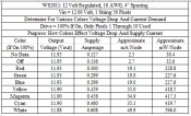
Here is some data I have for WS2811 strings. As previously mentioned, current values are close, not what I consider accurate; values should be within +/- 3 or 4 mA I think. Voltages are essentially 'dead-on' +/- a display count; mW is a calculation. Also as mentioned I am not completely comfortable with these results and intend on retesting. Cheers and Happy New Years everyone.
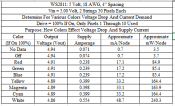
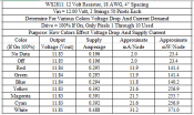
WS2811 5V.pngWS2811 12V Resistor.png
WS2811 12V Regulated.png

2020Dec30 Edit: The 5 Volt Pixel mW/Node calculation was 'corrected' Value is calculated as: (Vin + Vout)/2 * [mA/Node].
2021Jan18 Edit: Deleted (After all this time) the original 5 Volt png attachment that used/had the calculation error. Apologies to all.
 
Last edited:
Well, now I'm confused. Taking the 5V string...

no signal current (100 nodes) = 0.071A
no signal current (90 nodes) = 0.0639A
White on full (10 nodes) = 0.554A - 0.0639A = 0.4901A (current to string - 90 nodes no data)
current / node = 0.04901A
voltage to string = 4.86V
node power = 0.04901A * 4.86V = 0.238w or 238mw / node

Using off or 0,0,0 as the input data for all 100 nodes
off current (100 nodes) = 0.074A
off current (90 nodes) = 0.0666A
White on full (10 nodes) = 0.554A - 0.0666A = 0.4874A (current to string - 90 nodes off)
current / node = 0.04874A
voltage to string = 4.86V
node power = 0.04874A * 4.86V = 0.237w or 237mw / node


Using the second set of calculations for the 12V resistor string:
and off or 0,0,0 as the input data for all 100 nodes
off current (100 nodes) = 0.196A
off current (90 nodes) = 0.1764A
White on full (10 nodes) = 0.488A - 0.1764A = 0.3116A (current to string - 90 nodes off)
current / node = 0.03116A
voltage to string = 11.81V
node power = 0.03116A * 11.81V = 0.368w or 368mw / node

Using the second set of calculations for the 12V regulated string:
and off or 0,0,0 as the input data for all 100 nodes
off current (100 nodes) = 0.136A
off current (90 nodes) = 0.1224A
White on full (10 nodes) = 0.608A - 0.1224A = 0.4856A (current to string - 90 nodes off)
current / node = 0.04856A
voltage to string = 11.88V
node power = 0.04856A * 11.88V = 0.577w or 577mw / node

What confused me is that the power/node value for the 5V string was higher than that for the 12V resistor string. What astounds me is a regulator that dissipates the extra power is used. Taking the power ratio, and multiplying by the 5V string's voltage (4.86V * 577mw/237mw) is 11.83V, or darn close to what the 12V regulated string got. That means 7/12 of the power is overhead in a 12V regulated pixel prop (841w for a 2500 pixel megatree).
 
Last edited:
Or you can read it another way.
5V pixels need 5V or close to 4-6V
12V resistor pixels need close to 10-12V
12V regulated pixels need 7-13V
The WS2811 chip needs an average of 4-5V square wave to get a correct signal on the data.
There is no right or wrong
Every type has it’s own (good and bad), (do and don’t) etc.....
Every person has a preference
So to me it is, use what you have and work with it not against it
I have 5V smart, 12V dumb and smart
May add 24V dumb and DMX for 2021.
I enjoy making a show that every person likes different songs or effects, mix it up and enjoy the smiles
 
You're right that it is the end result that counts, and there are many paths to get there.
My goal is to get there as efficiently as possible. To me that means 5V, and some creative wiring, to keep the low voltage runs as short as possible.
 
The main way I do it is
From controller data and -ve/ground in a 0.5mm2 or 1mm2 or 1.5mm2, depending upon length cable, shortest run .5
From power supply a twin 1.5mm2 or 2.5mm2 but you must combine the 2 -ve’s together I do this at the start of the prop and the supply and controller -ve‘s are also tied together in the controller box
I then use the injection twin and carry it on to the start and finish of every string and tie all the +ve’s and -ve‘s together (fused at the start).
so cost of going 5V is extra cable.
But my whole show calculation for power in au for the month is $6.60 for 3602 LED’s
Enjoy the smiles.
 
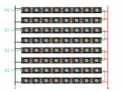
I'm playing with this:
matrix.png
The advantage is that line loss for each pixel is the same, meaning minimal color variation between the first and last pixels on the string. The disadvantage may be some extra wiring if power injection is required. As I said, I've got to play with it to prove it out.
 
I'm inclined to feel that you are over thinking creating a display. Without knowing what type of pixel you are planning to use or the number of pixels in a strand, I see nothing wrong with your plan to power the strands. Rather that trying to engineer a method to minimize color variations between pixels, would it not be easier to define how hard the pixels need driven, calculate power requirements, determine power injection, and build it? Another thought, with the data line chain first to second strand within each strand set, I wonder a bit about the data line voltage reference to the minus voltage.
 
If the ends are not to far apart power both ends with +&-
The voltage variation will be the same at both ends, but one will be more to +5v side and moving to the +0v side but be the same voltage difference (5 to 1 or 0 to 4) which may affect the data line.
 
All good points to ponder. My current project will use 60 pixel/m strip to create a 60 x 60 matrix, arranged as four strings of 900 pixels each. It will let me know if I'm on the right track.
 
Several clarifications to the chart data: No Data is all pixels commanded off followed by disconnection of the data line. This produces as close to the 'keep alive' current of a pixel as I can implement. The pixels were off as I verified that I can detect (see) a binary 1 to any R, G, or B. Off of course is a repetitive command binary 0 to all three colors. A slight current increase between those indicates the IC requires a small bit of energy to process the data stream.

Vout is the measured voltage at the end of the string. With all pixels off a small voltage drop can be seen along the string from the IC 'keep alive' currents. Vin to the string was held at either 5.00 or 12.00 with a linear (not switching) lab supply.
 
Is something wrong with the 'Approximate mW/Node' column for the 5V pixels? I think it should be equal to the mA/node multiplied by the supply voltage. It seems to be close for the 12V pixels but not the 5V. The values for the mA/node all seem reasonable but I would still recommend measuring it for the strings that you buy. There are some threads in which the pixels are running at higher current. Now I'm not sure whether these were the resistor type or the regulated type:
 
I see on the Facebook x lights group The majority of people that have had pixel fires or melt downs have been caused by regulated rather than resistor pixels. The maths seems to suggest otherwise. Does anyone else have a similar experience?
 
They all will burn.
It will always depend on the power you supply and the wire size and many other things.
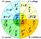
Back to basics. V=IxR or my favourite the power wheel.
Volts = the force
Amps = the flow
for the rest it is all in physics
1609313292290.png
I calculate the value of the current that I need for a Prop.
The problem with that is I don't take the string wire size into account.
The cheep strings/strip have a small wire size 0.3mm2 to 0.5mm2 max rating of about 5A
The 0.75mm2 (18AWG) is rated at very max of approx. 10A with a short duty cycle.
Now I add a couple of strings together and I need 15A or even just 10A.
If a short/dry joint (EG High resistance) anywhere along the string with power injections Iwi ll have a larger amount of Amps compared to the wire size and there is the problem.
Mine was when it was just powered up and no show so the pixels where not using Amps so the bad water logged pixel had the full fuse to contend with and I don't think for one second that the track on that little chip/board in there will be of considerable size to take the full Amps.
A 10A fuse will not blow at 10A unless it is a dead short of 0 ohms. I have seen a 10A fuse hold almost 20A if it increases very slowly.
So this malfunction in the solder/component becomes a higher resistance it uses more power/Amps which in turn then gets hotter and then the it just ends up in a cycle of more heat more Amps more heat etc.. etc..
I had a 5 volt pixel let out the magic smoke, water in the pixel creating corrosion and a hot joint.
It happens from 5V to 24,000V AC and DC. (Bigger volts bigger smoke)
As a sparky I should know better as I calculate the Circuit Breakers on wire size and length of cable. EG the fuse/CB is only there to protect the cable so it does not cause a fire, other devices are meant for personal and equipment safety.
So to do it absolutely correct every string should have its own protection but that is way to much work and cable.
This is my take on it all.
 
They all will burn.
It will always depend on the power you supply and the wire size and many other things.
Back to basics. V=IxR or my favourite the power wheel.
Volts = the force
Amps = the flow
for the rest it is all in physics
View attachment 16310
I calculate the value of the current that I need for a Prop.
The problem with that is I don't take the string wire size into account.
The cheep strings/strip have a small wire size 0.3mm2 to 0.5mm2 max rating of about 5A
The 0.75mm2 (18AWG) is rated at very max of approx. 10A with a short duty cycle.
Now I add a couple of strings together and I need 15A or even just 10A.
If a short/dry joint (EG High resistance) anywhere along the string with power injections Iwi ll have a larger amount of Amps compared to the wire size and there is the problem.
Mine was when it was just powered up and no show so the pixels where not using Amps so the bad water logged pixel had the full fuse to contend with and I don't think for one second that the track on that little chip/board in there will be of considerable size to take the full Amps.
A 10A fuse will not blow at 10A unless it is a dead short of 0 ohms. I have seen a 10A fuse hold almost 20A if it increases very slowly.
So this malfunction in the solder/component becomes a higher resistance it uses more power/Amps which in turn then gets hotter and then the it just ends up in a cycle of more heat more Amps more heat etc.. etc..
I had a 5 volt pixel let out the magic smoke, water in the pixel creating corrosion and a hot joint.
It happens from 5V to 24,000V AC and DC. (Bigger volts bigger smoke)
As a sparky I should know better as I calculate the Circuit Breakers on wire size and length of cable. EG the fuse/CB is only there to protect the cable so it does not cause a fire, other devices are meant for personal and equipment safety.
So to do it absolutely correct every string should have its own protection but that is way to much work and cable.
This is my take on it all.

Cheers mate
 
Is something wrong with the 'Approximate mW/Node' column for the 5V pixels? I think it should be equal to the mA/node multiplied by the supply voltage. It seems to be close for the 12V pixels but not the 5V. The values for the mA/node all seem reasonable but I would still recommend measuring it for the strings that you buy. There are some threads in which the pixels are running at higher current. Now I'm not sure whether these were the resistor type or the regulated type:

Apologies to everyone but yes the 5 Volt mW/Node calculation is/was not correct. It was pulled from one of the 12 Volt sheets (I use Excel). My post above has been edited with the revised chart.

I currently purchase strings from 2 sources, RGB Man and Wired Watts. For whatever reason I cannot purchased anything from China direct. As noted the strings are 18 AWG with 4 inch spacing. I have other data on the 3 types of strings but hesitate to post it as it is in my opinion not yet in an accurate form.

A general rule for pixel currents seems to be 60 mA to calculate a prop's amperage draw (I use 50 mA). That is close enough for the 5 Volt and 12 Volt Regulated pixels but I do not have a good explanation for the much lower 12 Resistor pixel values. Attempting to determine that is another project for 2021. One also needs to remember that subtle differences between manufacturer lot runs can cause different measurement values. Standardized component values come into play during the design as well.
 
Back
Top