That probably sounded bitter. Maybe because I was one of the newbies who wasted a lot of time and money only putting 100 pixels per port in year 1. The good news is I will never™ need more controllersWell I see someone’s out to prove a point
Navigation
Install the app
How to install the app on iOS
Follow along with the video below to see how to install our site as a web app on your home screen.
Note: This feature may not be available in some browsers.
More options
You are using an out of date browser. It may not display this or other websites correctly.
You should upgrade or use an alternative browser.
You should upgrade or use an alternative browser.
240V power points - max safe wattage when running your light show
- Thread starter janastas
- Start date
Just as another data point, I have 8 Mean Well SMPS on a dedicated C20 RCBO. They are a mix of wattages (200W - 350W) and various voltages (5V, 12V, 24V, 31V).
That 20A RCBO has tripped a few times over the past few seasons, always at the instant the DMX relays connect the SMPS units to the mains power. As far as I know it was a current trip, not an earth leakage trip each time.
So even with a dedicated 20A circuit, you can run into inrush issues. Sequencing the power supplies (switching on one by one with a small delay between) would eliminate that. Since there are 4 power supplies each in two different controller boxes (each with their own DMX relay) I can probably just do that staging in xlights as part of the turn on sequence.
I'll point out that the advice of @merryoncherry is correct - for 12V only, and only SOME resistor pixels, - and this is wildly dependent on the components the particular manufacturer has used.
Without pulling a particular pixel apart, or somehow identifying the resistor values, you will never know what the theoretical maximum that the design will consume.
For 5V pixels, and 12V pixels using regulators, then the other advice is also correct. They can and will draw up to the 16mA per colour - so 48mA total on full white.
Given this thread is about 5V design, then it's safe to assume that the design should follow those guidelines.
On the design aspect - I agree with both @merryoncherry and @battle79 - you can design for 100%, or you can design for lower, and hope that wire resistances will limit the current and not blow fuses. Both are valid. The former will cost more obviously, the latter can be valid as well.
Note however, if a fuse DOESN'T blow, it means the fuse is oversized for the gauge and length of of the wire. In Australia, for 240V household wiring, there are specific calculations that are made within the AS3000 standard (wiring rules) which state the maximum breaker you can put on a particular size wire, for a particular length, based on the current carrying capability of that wire, to ensure consistent tripping and prevent overheating. Whilst these don't apply here, I'm merely pointing out that length and gauge of the cable do need to be taken into account when selecting a fuse size. It has NOTHING to do with the number of pixels on it.
Also on the 'do I build to 100% or not' - again - I believe both are correct. As the results are very much installation dependent, when starting out, I would always suggest to build at 100%. Why? You can guarantee that nothing will come and bite you in the ass, except purchasing more than you need. Come year two, evaluate your design - see how much power your specific use case used, adjust as necessary, overcommit your power and cabling requirements as you wish or to however it works in your design. That one long run may need to have a large gauge cable, and may need to be run at 100% due to the placement of the prop - but this other item could possibly be downsized in brightness, and therefore more pixels can be thrown on that port, for example.
Basically there's no "one-size-fits-all" answer here.
 Haha
Haha
Without pulling a particular pixel apart, or somehow identifying the resistor values, you will never know what the theoretical maximum that the design will consume.
For 5V pixels, and 12V pixels using regulators, then the other advice is also correct. They can and will draw up to the 16mA per colour - so 48mA total on full white.
Given this thread is about 5V design, then it's safe to assume that the design should follow those guidelines.
On the design aspect - I agree with both @merryoncherry and @battle79 - you can design for 100%, or you can design for lower, and hope that wire resistances will limit the current and not blow fuses. Both are valid. The former will cost more obviously, the latter can be valid as well.
Note however, if a fuse DOESN'T blow, it means the fuse is oversized for the gauge and length of of the wire. In Australia, for 240V household wiring, there are specific calculations that are made within the AS3000 standard (wiring rules) which state the maximum breaker you can put on a particular size wire, for a particular length, based on the current carrying capability of that wire, to ensure consistent tripping and prevent overheating. Whilst these don't apply here, I'm merely pointing out that length and gauge of the cable do need to be taken into account when selecting a fuse size. It has NOTHING to do with the number of pixels on it.
Also on the 'do I build to 100% or not' - again - I believe both are correct. As the results are very much installation dependent, when starting out, I would always suggest to build at 100%. Why? You can guarantee that nothing will come and bite you in the ass, except purchasing more than you need. Come year two, evaluate your design - see how much power your specific use case used, adjust as necessary, overcommit your power and cabling requirements as you wish or to however it works in your design. That one long run may need to have a large gauge cable, and may need to be run at 100% due to the placement of the prop - but this other item could possibly be downsized in brightness, and therefore more pixels can be thrown on that port, for example.
Basically there's no "one-size-fits-all" answer here.
Careful, maybe you'll get reported for tax issues toowasted a lot of time and money only putting 100 pixels per port in year 1.
I would not recommend using thinner cabling to limit the current to the load in case of accidental 100% usage. The higher impedance (resistance) supply can cause instability by allowing the negative power connection to shift in relation to the data so much that the logic levels are invalid at higher brightness. The pixels can then lock up and fail to respond even if you drop the brightness levels again.
As @Skymaster alluded to above, thinner cabling can also invalidate your fusing strategy.
As @Skymaster alluded to above, thinner cabling can also invalidate your fusing strategy.
This seems a fact of life with 12V. While every bullet design I have tend to just flicker (read 0 instead of 1), 60/20 strip seems to lock on white. Data amps to the rescue... I've used dozens.The higher impedance (resistance) supply can cause instability by allowing the negative power connection to shift in relation to the data so much that the logic levels are invalid at higher brightness. The pixels can then lock up and fail to respond even if you drop the brightness levels again.
I am sure there are places in my setup where you could dead short and not blow a fuse, but unclear what harm this really is. I've seen other approaches that are scarier.As @Skymaster alluded to above, thinner cabling can also invalidate your fusing strategy.
Ultimately mitigated by having appropriately gauged wire for the current draw at hand to minimise voltage drop and riseThis seems a fact of life with 12V. While every bullet design I have tend to just flicker (read 0 instead of 1), 60/20 strip seems to lock on white. Data amps to the rescue... I've used dozens.
Data amps are a bandaid rather than fixing the underlying issue, but hey, lights blink, so who can argue with results! Haha
Indeed. But if you're that good at mitigating it, you may as well use 5V. 12V is for lazy people (such as myself) who define success as more blinks per hour of fussing about.Ultimately mitigated by having appropriately gauged wire for the current draw at hand to minimise voltage drop and rise
Data amps are a bandaid rather than fixing the underlying issue, but hey, lights blink, so who can argue with results! Haha
100% white is a cool effect to use sparingly, gets far more oohs and ahhs than all the tedious submodels I built for the HD propsYou wouldn't run 15000 pixels at 100% brightness as that would be soooooooooo much light.
FWIW, if you deduct the pixels on the back of the house, the ones off screen to the left, and the ones connected to the controller that was too busy to respond to ARP and stopped getting packets, you're probably looking at 70-75k on full white there.
If you think about it, it isn't that much light. The relationship between amount of light and apparent brightness is not linear, you have to generate a lot more light to look incrementally brighter. Direct sunlight on a clear day at reflects off a white object at a maximum of 1000W/square meter. A really HD prop may have 1000 pixels in a square meter, and once you deduct for inefficiency that may put out ~50W/square meter. Standing back from the house, the average is well below this number.
I would always suggest to build at 100%.
I build to run at 100% but not in perpetuity. This means plenty of DC PSUs, but I can't justify the electrical work to run at 100% white for extended periods of time. (Thanks to c3controls for letting me rip off their diagrams without permission
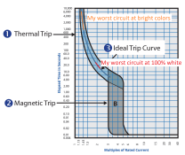
While we're at it, these diagrams also explain the inrush problem. That circuit has 21 PSUs on it, and no problem with inrush. But I had another that had only 16 PSUs and could not handle the inrush.
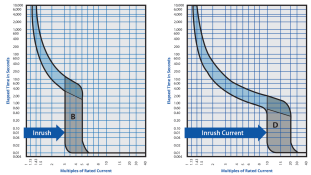
One possibility is that the breakers differed in their trip curves (I don't have the spec sheets for the breakers). Another possibility is that the resistance of the long extension cord limited the inrush. Or a combination of the two.
You just put up a B and D Type Breaker Trip Curve, in Aus, the standing install is a C Curve Breaker, with high inrush motors being installed on a D curve, Anything other than C curved are rarely used within Domiestic Installs, unless requested/specific install requirement.
This is absolutely false, and newbies who believe it end up massively overprovisioning power and wasting time and money on PSUs and wires. And, this will be partly your fault, as you are a respected community member who repeats the claims over and over. Read the spec sheets or, look at the board design, or better yet, measure them with a meter. All three will point to the same conclusion.
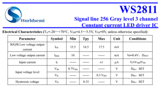
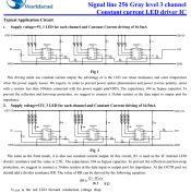
Spec sheet (and this is way high, we'll get to that later, and to why it is 10mA per color):
View attachment 22141
I was wrong.
My presumption was (based on the WS2811 datasheet) that 12 regulator pixels and 12V resistor pixels both used the same internal constant current source within the WS2811 chip. The constant current source is there so that any variations in voltage are accounted for and as long as the voltage available to the led is higher than than the forward voltage of the led then every led (within QC variations) will be the same RGB colour and the same brightness. The easy way to check this is with a variable power supply and a current meter. With a string of 5V leds you can adjust the voltage from 5V down to 4V or so and at full 100% white you will get a current of about 2.75A (50 nodes). This indicates that the leds are being controlled by the 18.5mA per colour (later changed to 16.5mA/colour) that they are meant to be controlled with. With the first generation of 12V pixels they used the exact circuit for 12V as is in the WS2811 datasheet and there are threads on ACL and DIYC 2016-18 where the 18.5mA/colour at 12V has been discussed and measured.
Sometime possibly around 2018 someone with poor understanding of how pixels are meant to work decided to put 3 resistors in series with the 3 leds in the pixel to reduce the current. It does precisely that but at the expense of not having a linear dimming curve and uniform colour. On top of that there is absolutely no way of calculating accurately the power usage of a 12V display as the current is very dependent on the voltage.
What has also happened with the changeover from the original 12V (with chip fed via resistor rather than regulator) and the regulator style compared to the resistor inline with the leds pixels is that the brightness for a given 0-255 brightness level on a gen1/regulator pixel is double or more than what a resistor limited pixel is. ie 30% brightness on a 5V pixel, gen1 12V pixel or regulated pixel will be twice that of a 12V series limited pixel. Once you start dropping the voltage as you go down the string the resistor 12V pixels will dim at a far greater rate than the others will. The first gen 12V pixels could drop from 12V down to about 3.5V without losing brightness or changing colour.
First gen 12V pixel nodes and 12 V regulator nodes will sometimes have a specification that says 0.6W or 0.66W per pixel.
5V pixels will generally say 0.3W per pixel
12V resistor pixels will say something like 0.36W
Not sure whether the person's understanding was poor or not, but these consequences are as you say. It's not elegant and the color and brightness aren't consistent. On the other hand, one might appreciate it as a convenient workaround for pixels that were designed to be too bright in the first place, and one that is quite suitable for lazy people like me. (It'd be great if they'd just make a chip that would current-limit to 8mA, and could dissipate 8mA * 9V per channel of heat, so we could run 12V direct. Then again, GS8208.)Sometime possibly around 2018 someone with poor understanding of how pixels are meant to work decided to put 3 resistors in series with the 3 leds in the pixel to reduce the current. It does precisely that but at the expense of not having a linear dimming curve and uniform colour.
Anyway, the effect is not that bad. You can see significant dimming between 12V and 4V, and a noticeable greenish hue.
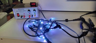
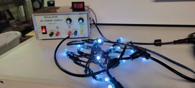
I don't think mine go below 8V (based on testing scenarios in the lab, but can't prove that in the field of course), and it would only happen when the whole string is full white, and then people generally can't tell because their eyes haven't adjusted.
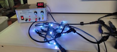
If you have full red with white sparkles, which does happen often enough (and is sufficiently intense), you'd be at around 10V.
Howdy all,
Now that the blinky season is over just doing some planning for 2023 and looking at purchasing new gear to play with.
One of the questions that popped into my head is the max safe wattage you should be able to get from a standard 240V power point in Austalia.
From what I've read online standard 240V power points should be able to handle max 10A current. (P = VI so 240 x 10 = 2400W)
For my 5V light show if running at 100% brightness and the max current per pixel is 0.06A we're looking at 0.3W per pixel (8,000 pixels off a single power point), I usually run at about 30% brightness so assuming I could easily triple the number of pixels to 24,000 pixels!
Not that I'm going to get to 8,000/24,000 pixels any time soon but should I dial down the expecations to 75% of this and say 6,000/18000 would be a safe bet?
not sure if it will help but i use this power meter from jaycar to workout how much i am pulling from the mains and then spread the load out over a few different points.
Mains Power Meter | Jaycar Electronics
This intelligent power meter simply plugs into a normal power point (GPO) and turns it into a real-time power monitoring outlet. You can enter the loc...
OK so I'm trying to recalculate my GPO requirements for this season knowing that I'm adding almost 5k pixels to my existing 6.5k pixels (plus panels.)
I somehow currently run everything from 2x double GPOs without issue. 1st GPO is in the garage which has a powerboard and extension leads all on an AC timer and back onto our old lounge room, so appears to be run on our "right side" house circuit. The 2nd was put in a few years ago on the outside of our bedroom wall on the "left side" of our house and has 2x AC timers. All 3x timers are set 1 min apart so the show is powered in stages within 5 mins of show start (the FPP Pi and network switch stay powered 24/7 from the right garage GPO.)
I have a spreadsheet to track the PSUs and number of pixels on each so I know which ones are getting too heavily loaded. I calculate this using David AVDs calculator and I know this is all based on 100% white but I never run full brightness (but as mentioned previously is always good to plan for the worst.) Most of my PSUs are MW LRS 5v, with a couple of Ray 5v and 12v in the mix. Assuming they all use 3.4A, I currently plan to 9 PSUs (or 30.6A) on the right side and 6 PSUs (or 20.4A) on the left side.
Noting that "the maximum from a single socket is 10A" (I assume this is per plug so a double GPO can handle 2x 10A?) does this mean I'll need to add at least 1x more 10A GPO per side to safely handle a full brightness display? Given this is still currently sharing existing power circuits, would I be best to consider getting a dedicated circuit seperate from the rest of the house?
Goes without saying all electrical works will be conducted by a certified sparky, I do not play in this space nor do I condone anyone doing it DIY.
Correct. A double outlet can handle 20A. Note, however that the circuit may only be 16A or at most 20A. So that will be the limiting factor. You'll also need to account for anything else on the same circuit.Noting that "the maximum from a single socket is 10A" (I assume this is per plug so a double GPO can handle 2x 10A?) does this mean I'll need to add at least 1x more 10A GPO per side to safely handle a full brightness display? Given this is still currently sharing existing power circuits, would I be best to consider getting a dedicated circuit seperate from the rest of the house?
A dedicated circuit has benefits in that if there is an issue in the house, it won't take it blinky, and vice versa. You also then know that it's 100% available and the other half isn't going to turn on a hair dryer or kettle and overload the whole lot.
16A-20A of 240V ought to cover a lot of .3W 5V or 12V resistor pixels at 80% PSU efficiency... almost all of them really. (Not counting the panels.)

