240V power points - max safe wattage when running your light show

janastas

Full time elf
Joined
Nov 30, 2020
Messages
120
Howdy all,

Now that the blinky season is over just doing some planning for 2023 and looking at purchasing new gear to play with.

One of the questions that popped into my head is the max safe wattage you should be able to get from a standard 240V power point in Austalia.

From what I've read online standard 240V power points should be able to handle max 10A current. (P = VI so 240 x 10 = 2400W)

For my 5V light show if running at 100% brightness and the max current per pixel is 0.06A we're looking at 0.3W per pixel (8,000 pixels off a single power point), I usually run at about 30% brightness so assuming I could easily triple the number of pixels to 24,000 pixels!

Not that I'm going to get to 8,000/24,000 pixels any time soon but should I dial down the expecations to 75% of this and say 6,000/18000 would be a safe bet?
 

AAH

I love blinky lights :)
Community project designer
Joined
Dec 27, 2010
Messages
4,193
Location
Eaglehawk
Your numbers are about right with the exception that the efficiency of the power supplies hasn't been factored in. They are typically something like 90% efficient. You end up with about 2160W of usable power which at 55mA per WS2811 pixel gives you 7854 5V pixels per power point (it would be 3272 pixels if using 12V).
 

Skymaster

Crazy elf
Global moderator
Generous elf
Joined
Dec 19, 2021
Messages
1,074
Location
Western Sydney
Yes, the maximum from a single socket is 10A. The max from a circuit could be either 16A or 20A depending on the breaker that you've got in your switchboard.

Look at it from a power supply perspective. You need to take efficiency into account. So it's easier to look at the power supply data sheet.

Lets say you're using Meanwell LRS350s.
The data sheet (https://www.meanwell.com/Upload/PDF/LRS-350/LRS-350-SPEC.PDF) says that they have a typical AC current of 3.4A on the mains side, at full power. This equates to each power supply using 782W for 300W output, so 38% efficient - so you could safely run 3 of these at 100% off a single power point at 100%.
At 60A * 3 this is a total of 3750 pixels (180A / 0.048A per pixel) at full white, 100%

Now, the typical efficiency of the PSU stated though, is 83.5%. This is at a lower utilisation. Lets say 80% is standard.
For 300 * 80% = 240W output, they would use 240 / 83.5% = 287W = 1.24A per PSU, which is 8 per outlet.
This is therefore 8 * 60 * 80% = 384A / 0.048A = 8,000 pixels.

Edit: I will note that the 83.5% efficiency in the data sheet is not stated at what load, so I have just assumed 80% load. The efficiency falls off relatively quickly over this point.
 

janastas

Full time elf
Joined
Nov 30, 2020
Messages
120
Your numbers are about right with the exception that the efficiency of the power supplies hasn't been factored in. They are typically something like 90% efficient. You end up with about 2160W of usable power which at 55mA per WS2811 pixel gives you 7854 5V pixels per power point (it would be 3272 pixels if using 12V).
Thanks @AAH, I'm currently sitting at around 2700 pixels in my current show after two seasons of blinky's so still have a way to go until I get even close to 8,000 pixels.
 
  • Like
Reactions: AAH

Skymaster

Crazy elf
Global moderator
Generous elf
Joined
Dec 19, 2021
Messages
1,074
Location
Western Sydney
I will note that on my show (~6k pixels @ 5V) - due to wire losses etc, when pushing my show to 100% full white, from a test pattern (which is 100% on some props, down to 50% on others) - I was drawing around 1.1kW = 5A from the power point total.
When the show was running during the light hours at this brightness, it was opping at about 500W. Even later at night once the brightness dropped down more, I was down to at around 200-300W depending on sequence.
 

Notenoughlights

400,000+ twinkly lights
Joined
Oct 16, 2016
Messages
658
Location
Christchurch, New Zealand
Don't forget that a lot of circuits in your house tend to run to other power points as well, this will also eat into your maximum draw depending on what is plugged in and running. If you intend to have a lot of draw from blinky, perhaps work out what circuits in your house go to what plugs, and spread the load across a couple of circuits, or if you really are wanting to get serious in the hobby, consider a dedicated circuit or two fed to the exterior of your house just for lights (and other things during the rest of the year, outdoor sockets are always handy)
 

Skymaster

Crazy elf
Global moderator
Generous elf
Joined
Dec 19, 2021
Messages
1,074
Location
Western Sydney
consider a dedicated circuit or two fed to the exterior of your house just for lights
This is also handy if you've got other critical things on the same circuit.
RCDs (aka safety switches, GFCIs etc) may trip if your 230V connections get damp (or various other reasons whilst outdoors, bugs etc), and you won't want to be taking out the fridge or the wife's Netflix :)
Having them on dedicated RCBOs is the best way to avoid any nuisance trips for the rest of the house.
 

merryoncherry

Senior elf
Joined
Apr 2, 2022
Messages
645
Location
Cherry St., Hudson MA USA
it would be 3272 pixels if using 12V
Basing this on 2400W of 20A*120V, not 10A*240V, but...

3272 is way low unless you are using 12V regulated pixels with no wire loss. 12V resistor pixels with wire loss counted would be at least 3x that; an appreciable difference for planning purposes. From experience, 16K is too many as patterns held for long periods of time with sky blue, tan, or half white and half red will trip the breaker after 10 seconds. With 12K pixels on there it will hold full white for a couple seconds no problem or any bright color held in any sequence I have, and with 10k pixels it will hold full white indefinitely.
 

AAH

I love blinky lights :)
Community project designer
Joined
Dec 27, 2010
Messages
4,193
Location
Eaglehawk
Basing this on 2400W of 20A*120V, not 10A*240V, but...

3272 is way low unless you are using 12V regulated pixels with no wire loss. 12V resistor pixels with wire loss counted would be at least 3x that; an appreciable difference for planning purposes. From experience, 16K is too many as patterns held for long periods of time with sky blue, tan, or half white and half red will trip the breaker after 10 seconds. With 12K pixels on there it will hold full white for a couple seconds no problem or any bright color held in any sequence I have, and with 10k pixels it will hold full white indefinitely.
The current of resistor and regulator 12V pixels is exceptionally close to being the same and the voltage drop down the wire makes very little difference to the power. The voltage drop means that there is power dissipated in the wires rather than in the pixel. Up until the point where the colours start to become pastel towards the end of the string the current remains the same as well. It's the global brightness that makes a difference to the current and wattage.
Aussie power points are 240V 10A and are typically on a 20A circuit breaker. I have no knowledge of what current rating US power points and breakers/fuses are. In theory if nothing else was on the same circuit drawing any power then 1 double power point could use the full capacity of the 20A mains breaker and supply 15,000 5V pixels at 100% brightness. You wouldn't run 15000 pixels at 100% brightness as that would be soooooooooo much light.
 

battle79

Full time elf
Joined
Dec 8, 2012
Messages
465
Location
Chirnside Park, Victoria, AU
Guideline that I would follow when planning power requirements:-
1) Plan for full white 100%. Expect that at some point you will stuff up and run lights at full 100% (usually due to test mode on a board), everyone says they never will and eventually they will, I would almost guarantee that. At some point you will find yourself fault finding and run test mode. Mostly you will just end up with dim lights, but could easily pop the fuses on the DC cabling or melt down a PSU if unlucky.

2) Size cabling for 100%. Same principle as above. My advise is if you size the cable to carry enough current for full 100 White, than you will never have problems with it at 30%. I generally use 1.5mm extension lead cable with 3 pin ray wu connectors(or xconnect if you prefer) to get to props from controllers, and 1.5mmsq fig 8 or 2 core flex with 2 pin connectors for power injection cables.

2) How you switch on matters. Each PSU has an inrush current on start-up that can be 5-10 times the usual operating current. RCD/Circuit breakers are designed to take this in to account, but if you put more than 6 PSU (350W ea. 2100W total) on one circuit and turn them all on simultaneously, you might be happy, or you could run into issues. Typically it will likely work fine for a while and then start having issues. Similar to if you keep popping an RCD (say overloading kitchen cct) it will quickly start to trip even more often and then die. If you can turn on each one one at a time, than totally ignore this advise, just don't overload cct as normal.

3) Keep power away from the crowd. Goes without saying, but never hurts to remind. Personally, I've installed power points in my eaves so they are well protected from weather and nice and high out of the way. Now only need small 1mtr power leads to control boxes that are also up high. I do have one box at base of tree in garden that has a 12mtr lead back to the house and up to the eaves. On the subject of PSU's, they typically don't come with a lead attached and it definitely pays to get someone who knows what they doing to wire them up if you are at all unsure.

4) Network cables. Now seems a good time to also mention data, as it can also be run at same time as power by your electrician and be put on plates in the eaves just like a phone outlet in your house would be. Run them all back to a central location and you can put a f48 and run smart remotes, or install a switch and you can run full controllers at each location. Or any combination of the two.

The permanent cabling part of 3 & 4 are totally unnecessary, but are amazing if you can implement them. Label everything nicely and setup and pack up can become so much easier. My plan is to not have any cable longer than 3mtrs in my display next year, except the runs to my small garden tree. Even that might get a underground conduit if I get around to it (didn't happen last year, but was on the list).

Enjoy this fun hobby and stay safe people,
Rowan
 

Adsy

Full time elf
Joined
Aug 10, 2018
Messages
204
Location
Sheidow Park SA
I had to put an inline switch to stop a controller box from tripping multiple power supplies. If in doubt get a sparky to set something up specific for your needs :)
 

Goliath

Full time elf
Joined
Dec 31, 2014
Messages
166
Location
Gracemere
One of the first things I did when I started down this trail, was to get a Sparky to put a dedicated circuit in with switches in two places at the front of the house. There's a second circuit available too, with the powerpoint in the switchbox. If the rain somehow shorts my lights, Her Majesty's TV viewing will not be interrupted.
 

merryoncherry

Senior elf
Joined
Apr 2, 2022
Messages
645
Location
Cherry St., Hudson MA USA
The current of resistor and regulator 12V pixels is exceptionally close to being the same and the voltage drop down the wire makes very little difference to the power.
This is absolutely false, and newbies who believe it end up massively overprovisioning power and wasting time and money on PSUs and wires. And, this will be partly your fault, as you are a respected community member who repeats the claims over and over. Read the spec sheets or, look at the board design, or better yet, measure them with a meter. All three will point to the same conclusion.

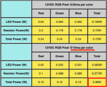
Spec sheet (and this is way high, we'll get to that later, and to why it is 10mA per color):
WS2811Configs.png

Regulated pixel design:
A string of 100 12V regulator pixels has its current limited to ~18mA per color by the WS2811 chip, with the voltage difference between 12V and the forward voltage of the LED (2-3V) going to wire resistance, linear regulator, and the WS2811 current limiter. A string of those will measure right around 5A, depending on brand (I've seen 4.7-5.2A for 100). That's where the .6-.7W number comes from, and it's where you'd derive a number like 3k-4k per PSU. It is also true in this configuration that the voltage drop down the wire doesn't matter much, but rather gives the linear regulator less power to dissipate; a good pixel design will be such that wire is thin and resistance keeps the fuse from blowing; the pixels will brown out before a fuse would blow.

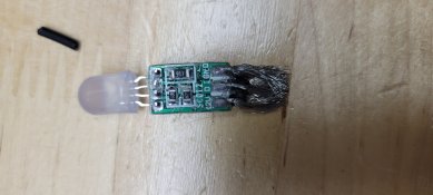
Resistor pixel design:
20220804_072104.jpg
Here, the behavior is different. The 12V encounters the following series of components: wire loss, WS2811, LED, and 820ohm resistor (910 ohm for red). At a full 12V (no wire loss), we can calculate the current, using blue/green (red is similar, but with a different forward voltage and current). First, the LED forward voltage is ~3V, so that leaves 9V. We will assume the voltage drop across the WS2811 is negligible (it is less than a volt). This means the current is determined by 9V/820ohm = 11mA. In reality I've never managed to measure over 10mA, could be voltage drop on the WS2811. Because the max current you could possibly get through the circuit is 11mA, the current limiter in the WS2811 isn't relevant. So, obviously, the power usage of the resistor pixel will be half of that of the regulator. I don't find this "exceptionally close", as you claim.

Another thing that happens is that as the voltage drops, the resistor pixel can no longer draw that full amperage. The current will be proportional: 10mA*(voltage - 4V) / 8V. Because of the 20-22ga wire, the effect of this is quite pronounced at full white. This gets to the third way of telling that resistors use less power, which is measuring them:

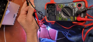
100 12V resistor pixels full white, powered from one end only, 2.2A (average of 22mA per pixel):
20220404_184543.jpg

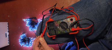
200 12V resistor pixels full white, powered from one end only, 3.10A (average of 16mA per pixel):
20220404_184707.jpg

So we see that voltage drop down the wire has cut the power significantly.
 

merryoncherry

Senior elf
Joined
Apr 2, 2022
Messages
645
Location
Cherry St., Hudson MA USA
Guideline that I would follow when planning power requirements:-
1) Plan for full white 100%. Expect that at some point you will stuff up and run lights at full 100% (usually due to test mode on a board), everyone says they never will and eventually they will, I would almost guarantee that. At some point you will find yourself fault finding and run test mode. Mostly you will just end up with dim lights, but could easily pop the fuses on the DC cabling or melt down a PSU if unlucky.

I use 12V resistor pixels mostly, so "good planning" means ensuring that I only end up with dim lights at 100%. This, counter to your #2 advice, means not using bigger wire than the pixel vendor supplies. That way, the thing dims out instead of drawing current. You could put 800 typical 12V resistor pixels in a series and it won't draw over 4A... but 100% white is gonna be dim, turn green, and possibly become flaky down the line.

The other comment is that if you do overload a Meanwell LRS PSU (and probably other brands), it has overcurrent protection and won't melt. At 110%, depending on temperature, it will go into "hiccup mode", at 140% it will do a lot of hiccupping. This is bad, but not that bad.

2) Size cabling for 100%. Same principle as above. My advise is if you size the cable to carry enough current for full 100 White, than you will never have problems with it at 30%. I generally use 1.5mm extension lead cable with 3 pin ray wu connectors(or xconnect if you prefer) to get to props from controllers, and 1.5mmsq fig 8 or 2 core flex with 2 pin connectors for power injection cables.

2) How you switch on matters. Each PSU has an inrush current on start-up that can be 5-10 times the usual operating current. RCD/Circuit breakers are designed to take this in to account, but if you put more than 6 PSU (350W ea. 2100W total) on one circuit and turn them all on simultaneously, you might be happy, or you could run into issues. Typically it will likely work fine for a while and then start having issues. Similar to if you keep popping an RCD (say overloading kitchen cct) it will quickly start to trip even more often and then die. If you can turn on each one one at a time, than totally ignore this advise, just don't overload cct as normal.

YMMV, but I have had some 120V 20A circuits where 16x 350W PSUs works, and some where 16 causes too much inrush current to be switched on simultaneously. Never had an inrush problem with 12 PSUs on a breaker. (Obviously those won't run at 100% without tripping the breaker... at least not for long.)
 

Kurt87

New elf
Joined
Dec 15, 2020
Messages
37
Location
East Branxton
This is absolutely false, and newbies who believe it end up massively overprovisioning power and wasting time and money on PSUs and wires. And, this will be partly your fault, as you are a respected community member who repeats the claims over and over. Read the spec sheets or, look at the board design, or better yet, measure them with a meter. All three will point to the same conclusion.

Spec sheet (and this is way high, we'll get to that later, and to why it is 10mA per color):
View attachment 22141

Regulated pixel design:
A string of 100 12V regulator pixels has its current limited to ~18mA per color by the WS2811 chip, with the voltage difference between 12V and the forward voltage of the LED (2-3V) going to wire resistance, linear regulator, and the WS2811 current limiter. A string of those will measure right around 5A, depending on brand (I've seen 4.7-5.2A for 100). That's where the .6-.7W number comes from, and it's where you'd derive a number like 3k-4k per PSU. It is also true in this configuration that the voltage drop down the wire doesn't matter much, but rather gives the linear regulator less power to dissipate; a good pixel design will be such that wire is thin and resistance keeps the fuse from blowing; the pixels will brown out before a fuse would blow.

Resistor pixel design:
View attachment 22143
Here, the behavior is different. The 12V encounters the following series of components: wire loss, WS2811, LED, and 820ohm resistor (910 ohm for red). At a full 12V (no wire loss), we can calculate the current, using blue/green (red is similar, but with a different forward voltage and current). First, the LED forward voltage is ~3V, so that leaves 9V. We will assume the voltage drop across the WS2811 is negligible (it is less than a volt). This means the current is determined by 9V/820ohm = 11mA. In reality I've never managed to measure over 10mA, could be voltage drop on the WS2811. Because the max current you could possibly get through the circuit is 11mA, the current limiter in the WS2811 isn't relevant. So, obviously, the power usage of the resistor pixel will be half of that of the regulator. I don't find this "exceptionally close", as you claim.

Another thing that happens is that as the voltage drops, the resistor pixel can no longer draw that full amperage. The current will be proportional: 10mA*(voltage - 4V) / 8V. Because of the 20-22ga wire, the effect of this is quite pronounced at full white. This gets to the third way of telling that resistors use less power, which is measuring them:

100 12V resistor pixels full white, powered from one end only, 2.2A (average of 22mA per pixel):
View attachment 22144

200 12V resistor pixels full white, powered from one end only, 3.10A (average of 16mA per pixel):
View attachment 22145

So we see that voltage drop down the wire has cut the power significantly.
Well I see someone’s out to prove a point
 
Top