3 Channel DC Controller (Pixel Input)

David_AVD

Grandpa Elf
Community project designer
Generous elf
Joined
Jun 12, 2010
Messages
4,681
Location
Victoria Point (Brisbane)
** This thread is now in the AVD section here.

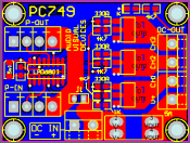
A lot of people are using pixels these days, so I designed a small PCB (38mm x 51mm) so they could add 3 channels of DC control and drive it from their pixel controller (TP3244, PIXAD8, etc).

davidavd 3 Channel DC Controller (WS2801 Pixel Input) pc748.png

This board accepts pixel data in the WS2801 format, so for example could be added to a mega tree to add a star topper using DC strip or other lights.

The maximum current capacity is 5 Amps between the 3 channels which should be more than enough. It can draw power from the 4 pin pixel I/O connectors or a dedicated DC input.

Once I get some prototypes made I'll post a picture of the completed board.
 

David_AVD

Grandpa Elf
Community project designer
Generous elf
Joined
Jun 12, 2010
Messages
4,681
Location
Victoria Point (Brisbane)
I'm also making another version based on the LPD6803 to cater for people who use 12V 6803 strip or 5V 6803 strings.
 

Attachments

  • davidavd 3 Channel DC Controller (LPD6803 based) pc749.png
    davidavd 3 Channel DC Controller (LPD6803 based) pc749.png
    12.6 KB · Views: 0

Superman

I Have C.L.A.P and its very infectious
Global moderator
Joined
May 29, 2010
Messages
1,778
Location
Ipswich-QLD
Question..
I plan to use one of these for a basic RGB star at the top of a ws2801 pixel tree. The ws2801 being a 5v system, I want make the star out of 12v RGB strip.
Would this mean that the board gets connected into the ws2801 string with v+,v-,data & clock and I inject 12v power into the board to power the 12v RGB strip without frying the whole thing.
 

David_AVD

Grandpa Elf
Community project designer
Generous elf
Joined
Jun 12, 2010
Messages
4,681
Location
Victoria Point (Brisbane)
I have provided a jumper to separate the pixel V+ from the DC output V+. This means you can use these boards on 5V pixel systems and still have 12V DC outputs with no issues. You will need to provide a 12V power source of course!
 

Superman

I Have C.L.A.P and its very infectious
Global moderator
Joined
May 29, 2010
Messages
1,778
Location
Ipswich-QLD
Thankyou, Great board, look forward to getting it when it is available. that certainty saves running two data cables to the tree
 

David_AVD

Grandpa Elf
Community project designer
Generous elf
Joined
Jun 12, 2010
Messages
4,681
Location
Victoria Point (Brisbane)
Yeah, could really be handy if all you have is pixel data nearby. Some folks may not even have a DMX source in their layout at all.
 

David_AVD

Grandpa Elf
Community project designer
Generous elf
Joined
Jun 12, 2010
Messages
4,681
Location
Victoria Point (Brisbane)
Maybe $20 or so fully built and tested at a guess. Depends on if I can justify getting boards made in bulk as small runs of PCBs are quite expensive.
 

bright spark

New elf
Joined
Mar 14, 2011
Messages
17
Hey guys, it seems that David and I were having very similar thoughts about this. I too have developed a LPD6803 controller. I was planning on using them along with a LOR CCR controller to basicly give me a 150 channel controller for a fraction of the cost. Now my design appears to to be quite similar to David's, although his has a few design floors from what I can see. At the moment mine are looking to be around the $10 mark each. I have 30amp mosfets, but without heatsinks I think 10amps would be more than enough for anyone. If anyone is interested feel free to contact me.
Aaron
 

bright spark

New elf
Joined
Mar 14, 2011
Messages
17
Sorry David, was past my bed time when I wrote that, the poor old brain gets a few run-time errors. What I have noticed with your circuit is that the logic supply is from the load supply and not from the pixel input. From this I assume the jumper is to drive the output side of things from the pixel supply. My only concern is that you may/will end up overloading the cable and therefore have a large voltage drop by the end of the last pixel. The second thing is it appears you have pulled the 'cmode' input LOW, so it is using the internal oscillator and not the clock input supplied. Lastly I'm not sure if its a huge concern, but you have no echo suppression on the clock and data signals. I havent fully tested whether it is of huge concern, but i have allowed for it anyway.
My design however is virtually much the same, since it is such a basic circuit to build. Although I have only allowed for all the pixel wiring to control the logic side of things, That way you can inject whatever voltage you wish for you lights and wont overload your pixel controller. Also I have allowed for 30amp mosfets, but that is with heatsinks and all that, but without would easily do 10 amps.
Also I am currently getting approx 270 boards printed up as we speak. My cards I'm sure I could pass on as a bare cost of around $2-3 each, depending on numbers. Or around $10 made up.
 
Top