48DMX board

Daemon

Apprentice elf
Joined
May 3, 2010
Messages
81
Location
Napier
Hi
Is there anyone on who could help me troubleshoot a Tiger 48 channel board please.


I attached a 24vdc power supply to it tonight to start sorting a few things out for Christmas and got a crackling sound and a small bit of smoke as well as the leds coming on.


Everything was connected properly yet somehow I got a short?


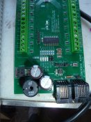
The smoke seemed to be coming from the bottom area near the capacitors. I have taken the board off its mount and it looks perfect.


I just need a schematic(which probably wont help me too much :)) and some assistance to continuity check and replace whatever has died.


If someone is proficient with these I would appreciate a hand.
 

David_AVD

Grandpa Elf
Community project designer
Generous elf
Joined
Jun 12, 2010
Messages
4,681
Location
Victoria Point (Brisbane)
Re: Tiger 48 DMX board

Hi Daemon,
Can't help you with a schematic, but I do know a bit about the Tiger 48.

Did you have anything hooked up to the outputs at the time it went crackle?

Also, where are you located? (not in your profile) Always good to know in case there's an ACL member nearby. :)
 

Daemon

Apprentice elf
Joined
May 3, 2010
Messages
81
Location
Napier
Hi David


I am in New Zealand. I will try to update my profile.


I had a channel crackle when I first got the board and that turned out to be a bad solder on one of the positives but this seems slightly more serious.


What is the black component down the bottom by the 2 capacitors? I havent run across that one before. It seems slightly loose and may be the culprit. I have tested all the resistor and visually assessed all the tracks and cannot see anything wrong at this stage.


I have a version 4.0 board if thats important too.


EDIT Sorry forgot to answer your question. I had hooked up 2 rainbow floods to the board. I had a 12v power supply hooked up with the negative to the common, the 12v + to the + of the floods and the flood - to the - side of the channels.
I believe it was you who gave me a diagram of how to hook it up last Christmas.
 

David_AVD

Grandpa Elf
Community project designer
Generous elf
Joined
Jun 12, 2010
Messages
4,681
Location
Victoria Point (Brisbane)
The "black thing near the capacitors" is probably the inductor for the regulator. Maybe check that the solder joints are not cracked.

It could be that you overloaded a channel and blew a transistor. I'm not sure how much current those lights draw. A short on the output would also blow the channel transistor.

I'm not certain of the part number of the output transistors. Phil would know, but I can't see you getting any info from him to be honest. I should have some spares around at work as he sent me some a while back.

Have you tried the board again since? Maybe check it with a small load on another channel to see if it still works.
 

Daemon

Apprentice elf
Joined
May 3, 2010
Messages
81
Location
Napier
At 100% intesity they draw 2.16A per flood and each flood is 3 channels so at 2.5A per channel output I think the 48ch dmx board should have been able to habdle it easily.
Plus I have hooked them up to the board before with no issues.


I will remove the 12v power supply and all the outputs and check the board again and get back to you.
 

Daemon

Apprentice elf
Joined
May 3, 2010
Messages
81
Location
Napier
Okay. I plugged the board back in empty and released some more magic smoke.
I first touched up the solder on the inductor and capacitors.


It seems most likely that it is the inductor because there is now a small black area around the left leg of it as you look at the back of the board.
 

Daemon

Apprentice elf
Joined
May 3, 2010
Messages
81
Location
Napier
I have attached 2 photos of the bottom of the board. I marked the offending legs in red and the small black patch in blue. Its the only trace damage I can see on the board.
 

Attachments

  • P1030442.JPG
    P1030442.JPG
    155.7 KB · Views: 27
  • P1030443.JPG
    P1030443.JPG
    354.6 KB · Views: 34

David_AVD

Grandpa Elf
Community project designer
Generous elf
Joined
Jun 12, 2010
Messages
4,681
Location
Victoria Point (Brisbane)
It's hard to see exactly, but some of the solder joints look like they need reflowing. They should have a uniform appearance without bubbles or jagged bits. It could be that your iron is not hot enough or you are not letting the whole joint heat up enough to reflow properly.

Removing the inductor, cleaning up the area with solder wick and starting again may be the best course of action. The heavy tracks and plated holes don't make it any easier.
 

Daemon

Apprentice elf
Joined
May 3, 2010
Messages
81
Location
Napier
Okay. I removed the inductor and the legs were just too small to resolder it properly so I made a right angle header for it and resoldered it.
Now that it is moved slightly I can see that the smoke is coming from the small smd chip labelled as D4 that is up and to the left off the inductor.
There is no way to resolder that is there? so I may have to take drastic action and bypass it somehow?
 

David_AVD

Grandpa Elf
Community project designer
Generous elf
Joined
Jun 12, 2010
Messages
4,681
Location
Victoria Point (Brisbane)
As per my PM, it sounds like there's more wrong than the inductor and diode. I should be able to repair it for you but not sure if postage both ways would bee too much?
 

Daemon

Apprentice elf
Joined
May 3, 2010
Messages
81
Location
Napier
Thanks guys


David_AVD has kindly offered to have a look at it for me.
I sent it off to Aussie today.


Cheers
Steve
 
Top