- Thread starter
- #46
It's time for another update. Again I have to say that things are progressing but the code is still a while of being finished. I'd hoped that I could get it finished and sent up to the Brissie mini but time has again got away from me. This week is another interrupted week with the long weekend ending yesterday and me having to head to Melbourne to do some work on Wednesday. That leaves me with the rest of today and Thursday morning to finish the code if I was to get a board sent off in time. I'm now enough of a realist to realise that I still have huge amount of code to write and test.
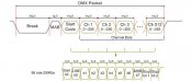
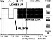
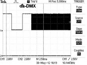
I've made a few mistakes that cost me a bit of time. As the saying goes "assumption is the mother of all stuffups". Well I made a couple of assumptions. The first was I had a quick look at the specs of an RS485 chip I had and assumed that it was going to do the same as the chip I had designed around. Oops. It turned out that the output was inverted and I didn't notice for a fair while and surprisingly enough I couldn't get data in. The second assumption was the the "lights up" program which generates dmx signals would generate a signal that is compliant with the dmx standard. After almost a full day of testing and wondering why I was getting strange results I discovered that it doesn't. See the attached pictures and you can see that there is a spike of data that shouldn't be there. As my code was checking for a break followed by a make after break (MAB) and resetting if there was a problem with the data then having a "glitch" in the MAB meant I was never getting valid code. I chose to ignore the "full on" requirement to detect the break followed by the MAB.
To make my assumptions worse if I hadn't made the assumption with the "lights up" I could have, and had tried to, invert the signal via software which would have fixed my first problem.
I am writing in the following cycles for the test mode to put things through their paces. I can't be bothered doing fades as there is enough code being used already. Each cycle will run followed by the next and it will then go back to the start.
1 SINGLE LED1 THEN 2 THEN 3 ----> 60 . @ 0.1S. TOTAL 6S
2 SINGLE R LED1 THEN 4 THEN 7 ETC @ 0.2S. TOTAL 4S
3 SINGLE G LED2 THEN 5 THEN 8 ETC @ 0.2S. TOTAL 4S
4 SINGLE B LED3 THEN 6 THEN 9 ETC @ 0.2S. TOTAL 4S
5 ALL RED LED 1 + LED 4 + LED 7 ETC @ 1S. TOTAL 1S
6 ALL GREEN LED 2 + LED 5 + LED 8 ETC @ 1S. TOTAL 1S
7 ALL BLUE LED 3 + LED 6 + LED 9 ETC @ 1S. TOTAL 1S
8 AQUA (G+B) LED 2 +LED 3 + LED 5 + LED 6 ETC @ 1S. TOTAL 1S
9 YELLOW (R+G) LED 1 + LED 2 + LED 4 + LED 5 ETC @ 1S. TOTAL 1S
10 PURPLE (R+B) LED 1 + LED 3 + LED 4 + LED 6 ETC @ 1S. TOTAL 1S
11 WHITE ALL LEDS ON @ 1S. TOTAL 1S
12 SINGLE W LED 1+2+3 THEN LED 4+5+6 @0.2S. TOTAL 4S
If anyone would like to see something different tested then now is the time to sing out. With the exception of fades I've ran through everything that i could think of.
Alan
")