ACL Strobe Building

drlucas said:
Ok. So maybe my power supply is marked wrong. I swap power and the strobe turns on solid white. Should it strobe on its own? When i reverse polarity nothing happens. Did I previously just kill my pic with the reverse and have to solder up another to test or is the light a sign of goodness and I need to use something else to control it.


drlucas, when you put the correct power on the strobe will start a Random flashing until power is removed.
They are self-controlling. Solid ON means it is damaged. Nothing means it's damaged OR a dry joint on a strobe leg.
Out of 144 I had 1 that smoked a chip (yep my first Magic smoke, several are dead thru in-attention when wiring and several that worked when I resoldered the strobe properly.
 
OK - one can hope for a bad solder joint.


I saw no smoke at all...I've only seen smoke before when I connected 12v to a 5v device once in mylife. From there I learned to read the numbers on the brick before connecting....which reminds me I have a cheap FM02 transmitter if anyone is interested...at least the LCD screen works still...<grin>


Did those that are "dead" on you come to life at all when you connect a pickit to it at all? I'll spend some good time this weekend, setup my desk with LOTS of light and give this another whirl.
 
drlucas said:
OK - one can hope for a bad solder joint.


I saw no smoke at all...I've only seen smoke before when I connected 12v to a 5v device once in mylife. From there I learned to read the numbers on the brick before connecting....which reminds me I have a cheap FM02 transmitter if anyone is interested...at least the LCD screen works still...<grin>


Did those that are "dead" on you come to life at all when you connect a pickit to it at all? I'll spend some good time this weekend, setup my desk with LOTS of light and give this another whirl.


Yes lots of light and good magnification. I had 2 pairs of glasses and a strong magnifying glass as well.
DVD-Extra-Mr-Magoo-more-cartoons-HCJ06JP-x-large.jpg

I've got some I have not worked through to see what is dead but happy that I've got some 130 odd going on my first serious electronic build for 50+ years :D [SIZE=78%]. [/SIZE][/size]Certainly enjoyed the challenge and am enjoying my first year of pixels.[size=78%]
 
Well I have verified the power supply is labeled correctly. I'll go over things with a good set of eyes and look for bridges that are red circled in the manual. That is where I think my issue lies. Last night was more sorting out channels and sequencing like crazy to have a Halloween show. Spent the last month or so fixing up my matrix and getting synchronized video to work with the raspberry pi. I'm sure I'll either have more pictures of things nor working or I'll have video of strobes posted by end of weekend
 
Quick update....I have one of the strobes working now. I'll see if any of the first three can be saved now that I know what I'm doing.


Sadly with the rain last night we had maybe 40 kids tops visit for the halloween show and today got COLD as heck (-2 sigh) however....the good news is it is November so I can start with the christmas setup :)
 
OK... now I'm confused.


I built two - both worked standalone. I then connect two of them together. both work for about 2 seconds and then nothing.


This really shouldn't be that hard.
 
It definitely shouldn't be too hard. As long as you hook them up in parallel and supply 3.7V to 5.3V they should strobe away madly. It might be worth posting a photo of how they are linked together.
 
I'll post up pics later today just built two more and they are working fine alone. I have my multimeter connected steady to power source and I'm between 4.96 and 5.00 so I should be fine. One thing I may have done but not sure it would have an impact is my power supply is a 5v ray wu special. I have when screwing down my multimeter noticed my screwdriver handle touched the chassis of the power supply when I was screwing down the + side and it caused a ground fault and reset the PS. I wonder if when I was testing the strobes if I had the -ve wire on the post and then hit the +ve on the chassis. Wonder if being careless like that caused my issue. Anyways I'll post pics before I connect power to the pair of strobes for comment.
 
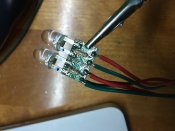
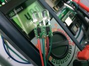
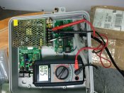
Here are three pictures of what i'm working with.


One is the multimetre connected to the power supply.
One is the front (chip) of the board showing red(+) and green (-)
One is the back (resistor) side of the board showing red(+) and green (-)


The path goes like this..


Power supply to chip side of first strobe. Then resistor side of that board to chip side of the next strobe.


Is this the correct way to join them?
 

Attachments

  • IMG_2386.JPG
    IMG_2386.JPG
    1.4 MB · Views: 37
  • IMG_2385.JPG
    IMG_2385.JPG
    1.4 MB · Views: 31
  • IMG_2384.JPG
    IMG_2384.JPG
    2.2 MB · Views: 31
That looks correct to me. The left hand led looks like the left hand lead isn't fully wetted and in fact most of the led joints look a little dry but I doubt that's an issue. Clipping your helping hands things on where you have it clipped is possibly an issue though as the pads that you're clipped onto is the ICSP header and I'd have to look at the pins but is possible you're on the ground and reset pins. Clipping onto the lead of a led is probably safer.
You should be able to carefully measure the 5V at the 2 spots where the strobes are powered.
 
AAH said:
That looks correct to me. The left hand led looks like the left hand lead isn't fully wetted and in fact most of the led joints look a little dry but I doubt that's an issue. Clipping your helping hands things on where you have it clipped is possibly an issue though as the pads that you're clipped onto is the ICSP header and I'd have to look at the pins but is possible you're on the ground and reset pins. Clipping onto the lead of a led is probably safer.
You should be able to carefully measure the 5V at the 2 spots where the strobes are powered.


Those joints do look dry. Not being smart here but they look like my early ones and I found even the ones I thought were good did not work as they had no contact.
The solder, or sodder in Northern parts of the world ;) , needed to have good flow and "run" up the leg, if that is clear.,
 
Don't get me started on the inability of Yanks to pronounce the l in solder and the 2nd i in aluminium.
 
The helping hands picture was just to get a picture of the board off the table (light reflection issue with the iPhone). However the strobe and the chip. I've found they easily fall off with a slight twist. Does anyone have a good close up high quality picture of the strobe led and their solder skills? I think I am going light on the solder. I also use the stuff with the flux mixed in - same thing I use for assembly of the Lynx hardware. Is that the wrong stuff to use?
 
are you putting solder on the board first then putting the led on the board and heating the led leg and letting the solder surround the led leg. I had my temp at 310 degrees and worked great
 
Yes - I'm tinning the pad on the board (both - and + sides) then heating the underside of the leg and using a pair of pliers or helping hands to get it to sit flat on the board. I am however not heating the led itself or really letting it flow onto the top of the leg. That I suspect is where much of my problems are coming from. What is the tolerance for heat on those legs...can I heat it for a good 10sec or so without damaging it?
 
Back
Top