nzlongfellow
Dennis from NZ
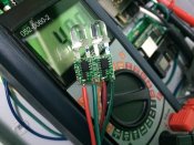
drlucas said:Ok. So maybe my power supply is marked wrong. I swap power and the strobe turns on solid white. Should it strobe on its own? When i reverse polarity nothing happens. Did I previously just kill my pic with the reverse and have to solder up another to test or is the light a sign of goodness and I need to use something else to control it.
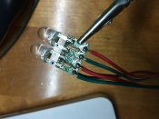
drlucas, when you put the correct power on the strobe will start a Random flashing until power is removed.
They are self-controlling. Solid ON means it is damaged. Nothing means it's damaged OR a dry joint on a strobe leg.
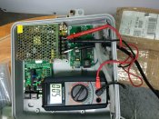
Out of 144 I had 1 that smoked a chip (yep my first Magic smoke, several are dead thru in-attention when wiring and several that worked when I resoldered the strobe properly.