Closed ACL Strobe Mk 2 bulk buy - ends 12 September 2014

Status
Not open for further replies.
Bulk buy close date
Sep 12, 2014

cscool36

Full time elf
Joined
Jan 9, 2011
Messages
167
Location
Belrose NSW
Did you get the led from E14. if so what would be the part number.
Thanks
Colin

AAH said:
I do have some PICs. Both the PICs and the NUD led driver are available from Element 14. The prices aren't especially cheap as that's where I got the bits for the protos.
 

AAH

I love blinky lights :)
Community project designer
Joined
Dec 27, 2010
Messages
4,188
Location
Eaglehawk
The LEDs came from Ray Wu. I have no idea what his part number is for them as we worked out what leds I needed via a session of chat on Aliexpress.
 

AAH

I love blinky lights :)
Community project designer
Joined
Dec 27, 2010
Messages
4,188
Location
Eaglehawk
I have added a bit more info on the wiki page including firmware hexfiles for the Mk2 strobe and also the firmware that would suit the TPR1 strobes.
I have added a bit more info to the assembly manual but won't update the wiki with it until I add stuff like wires, controlling strobes via a dimmer, siliconing or potting the pcbs etc.

[attachimg=1]
 

Attachments

  • Rough as guts assembly guide 1.1.pdf
    3.9 MB · Views: 36

Bird

LOR user
Joined
Nov 8, 2011
Messages
1,746
Location
Cincinnati, Ohio, USA
All North American packages shipped. Any issues let me know. Now all I have to do is wait for the rest of my bits to show up so I can stare at the pile for the next year or so. Finally got around to picking up the assembled Mk1 strobes last week. :)
 

arw01

Full time elf
Joined
Dec 30, 2013
Messages
384
Location
Eastern Washington
Mine arrived yesterday..


I'm fascinated with the "packing" peanuts, those are the bomb. That's a patented Australian invention as I've never seen them before in a the packages in the states. Much nicer than chasing packing peanuts around the driveway in the wind!


Have to figure out when I have time to solder these up and then deploy some to see!
 

Skunberg

Full time elf
Joined
Jul 10, 2010
Messages
194
Location
Eagan
Bird said:
All North American packages shipped. Any issues let me know. Now all I have to do is wait for the rest of my bits to show up so I can stare at the pile for the next year or so. Finally got around to picking up the assembled Mk1 strobes last week. :)


Is that last years Mk1 or the first round?
 

Bird

LOR user
Joined
Nov 8, 2011
Messages
1,746
Location
Cincinnati, Ohio, USA
Skunberg said:
Bird said:
All North American packages shipped. Any issues let me know. Now all I have to do is wait for the rest of my bits to show up so I can stare at the pile for the next year or so. Finally got around to picking up the assembled Mk1 strobes last week. :)

Is that last years Mk1 or the first round?
MK1 was summer of 2012 :)
 

nzlongfellow

Dennis from NZ
Joined
Jan 2, 2014
Messages
538
Location
Lepperton, Taranaki
AAH said:
I've got a pounding headache so you won't get too much sense out of me. The 27 channel board requires about 8V for it to work without modification. You can mod it to work off 5V if you really have to. If you have a higher voltage available then you can run the 27ch board off 8V or higher and connect the strobes to 5V either through a buck converter or else a 5V power supply with the V- commoned. There's an example of how to do this in the wiki, in the ACL101 and also in all of my user manuals for boards.


OK.
Done the following testing.
Set xLights to "background only" at 255 intensity. 12V at +V ternimals.


1) I connected 5V and 12V as per the attached doc.
No strobes. (Jumper -V 1 and PS -V and full illumination and strobes.)


2) Next tried Buck Converter connected to 12V supply then out to strobe then back to terminal 1. No go.


3) Next tried Buck Converter across board +V1 and -V 1 and strobe worked but dull.


There is 120 Ohms between -V terminals 1 - 27 and the PS -V terminal.
Seems very high. That is why 3) above is dull I suspect.


Seems a high resistance for the -V switch. ??? Open to any answers (as always).
 

Attachments

  • 5 and 12 Volt supply.docx
    63.1 KB · Views: 6

AAH

I love blinky lights :)
Community project designer
Joined
Dec 27, 2010
Messages
4,188
Location
Eaglehawk
[rant]FYI I absolutely despise M$ Word. I hate that it isn't backwards compatible and that the people who are stupid enough to use it send it out in emails and in documents assuming that everyone else has the same version of this horrendous program. [/end rant]

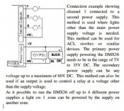
The buck converter needs to be connected with the incoming power supply to a source of greater than 10V depending on the buck converter. If the 27ch board is running off 12V then that is fine. The +ve for your strobes would connect to the output (5V) of the buck converter.
The below super rough edit of the picture shows how the buck converter would connect. The buck converter is powered by the 12V or 24V etc that the board runs from. The 5V output supplies the strobes and the -ve for the strobes is switches by the DC dimmer channel.
 

Attachments

  • Buck.jpg
    Buck.jpg
    95.3 KB · Views: 19

nzlongfellow

Dennis from NZ
Joined
Jan 2, 2014
Messages
538
Location
Lepperton, Taranaki
AAH said:
[rant]FYI I absolutely despise M$ Word. I hate that it isn't backwards compatible and that the people who are stupid enough to use it send it out in emails and in documents assuming that everyone else has the same version of this horrendous program. [/end rant]

The buck converter needs to be connected with the incoming power supply to a source of greater than 10V depending on the buck converter. If the 27ch board is running off 12V then that is fine. The +ve for your strobes would connect to the output (5V) of the buck converter.
The below super rough edit of the picture shows how the buck converter would connect. The buck converter is powered by the 12V or 24V etc that the board runs from. The 5V output supplies the strobes and the -ve for the strobes is switches by the DC dimmer channel.


Thanks Alan, sorry I should have done a PDF at least, but I also have a Samsung 8)


Using the controller to provide the -V path for the 5V is the problem in all the differing set-ups.
I think the whole problem I have is that xLights is RGB based and not DMX and the -V on the board is being controlled as such so is not a "true" path and the Voltage drop is too great.


I will try and set up LSP and see if that gives the same issue.
 

dougd

Full time elf
Joined
Jan 24, 2012
Messages
135
Location
Cleveland, Tennessee
So far my success rate has been near perfect.


Question Alan if you can answer. If you get the power reversed even though you clearly color coded the wires to make sure that wouldn't happen. What goes bad the chip, led, or both?
 

nzlongfellow

Dennis from NZ
Joined
Jan 2, 2014
Messages
538
Location
Lepperton, Taranaki
OK I have found a work-around for 27Channel controller and the Strobes.


It would appear the current through the ACL Stobe will not activate the MOSFET correctly when the 0V of the strobe is connected to it. I have 12V powering the board.


When I connected the Buck converter 0V to the same controller terminal as the strobe 0V I have full control and full colour (color for our other friends :D ).
I have only been connecting 1 strobe so if more are daisy chained then the problem may go away.


So for now I will fit a Buck converter to each terminal I want for the strobes unless multiple strobes per terminal fixes the problem.
 
Status
Not open for further replies.
Top