Connecting a linear actuator (linak) to a dimmer

Every relay I've ever used in the last 40 years has been break before make.

You'd have to look hard to find a make before break type.
 
Sorry if I’ve missed something but, as I’ve read on a lot of other threads they way people keep saying ‘make before break’ I thought it must have been big thing.

I’ve only ever had troubles with switches not breaking before making and going bang.
 
Every relay I've ever used in the last 40 years has been break before make.

You'd have to look hard to find a make before break type.
I've not heard this term before, is this just Normally Open contacts or something different entirely?
 
I've not heard this term before, is this just Normally Open contacts or something different entirely?
Kurt87 mentioned them early in the thread.

I’ve heard of late break normally close contacts and early make normally open contacts, but never with a SPDT contact.

I did only start my trade in 1999 though
 
Break before make (BBM) means the moving contact is totally clear of one end contact before it connects to the other. So there's a very small point in the switch (or relay) actuation where the COM terminal is connected to neither the NC or NO pins.

Make before break (MBB) is quite rare and only used for a few very specific applications that desire that the COM terminal never floats. In that type, the NC and NO terminals are very briefly connected together (via the moving contact) as the switch (or relay) passes from one state to the other.

MBB rotary switches are sometimes used for audio input selectors so you don't get a "pop" when switching from one source to another.
 
Yea sorry if I opened up a can of worms ... wasn’t my intention. just simply wanted you to be aware of the possibility of this issue when switching between positive and negative lines especially if it’s a cheap Rough as guts made relay which are not reliable and especially with a scenario where it may be making a lot of state changes where a welded contact could be possible over time
 
Yea sorry if I opened up a can of worms ... wasn’t my intention. just simply wanted you to be aware of the possibility of this issue when switching between positive and negative lines especially if it’s a cheap Rough as guts made relay which are not reliable and especially with a scenario where it may be making a lot of state changes where a welded contact could be possible over time
Apologies not really necessary I think. A can of worms; perhaps.

For those who do not know, the term is not seen very often any more due I think to the increase in digital control and solid state power circuits. The need for open/break before make came about mostly from relays and contactors switching high amperage devices. As David indicated, make before break is rather uncommon although devices are still used to an extent in today's industry mostly for push button and selector switch operators (called keycodes usually); AB (Allan Bradley), Square D, and Cutler Hammer for example. But even there physical devices are being replaced by 'soft' devices (touchscreens).
Reversing motor contactors still use both mechanical and electrical interlocks. But they are not absolute in their function. I have seen slop in the mechanical interlock physically lock-up a contactor with both sides partially 'activated' The contact armatures were not far enough to open the electrical interlock and thankfully not far enough to close the power contacts. During the days of relay controls and needless to say that reversing contactor was quickly replaced.

But to the topic, it is in my opinion still necessary when switching power loads to implement interlocks both in software and if possible hardware. For a software control feedback from the power contactor for failure detection is also advisable. So in an ideal situation 2 NC contacts, one for opposed interlock, the other for failsafe feedback (in addition to contacts for power switching).
 
Yea sorry if I opened up a can of worms ... wasn’t my intention. just simply wanted you to be aware of the possibility of this issue when switching between positive and negative lines especially if it’s a cheap Rough as guts made relay which are not reliable and especially with a scenario where it may be making a lot of state changes where a welded contact could be possible over time
It’s all good.

What we have discovered is a difference in hazard perception and risk analysis. Everyone perceives hazards, their risks and the likliehood of it occurring differently. It doesn’t make anyone right or wrong.


Personally, I perceive the issue you highlighted as a bigger risk than my proposed wiring issue. I’ve seen some ELV control only interlocked in PLC with no electrical wiring or mechanical interlocks and never had an issue. Can I program a dmx relay output in a similar manner is yet to be confirmed.
 
Can I program a dmx relay output in a similar manner is yet to be confirmed.
I would say yes, looking at @AAH op he mentions the use of DC dimmers to control a relay by sending signals of 0 and 100% value curves. Then looking at his shop he has DC Dimmer boards with ws2811 pixel data or dmx data control.
 
I would say yes, looking at @AAH op he mentions the use of DC dimmers to control a relay by sending signals of 0 and 100% value curves. Then looking at his shop he has DC Dimmer boards with ws2811 pixel data or dmx data control.
Do-able this way but not really necessary as there are DMX On/Off controllers. Blue Point Engineering makes one with 10 Volt 200 mAmp outputs; intended for SSRs (solid state relay) to control 120 VAC it seems. US manufacturer I think. Would be surprised if something similar is not available in Australia.

Myself, if I was thinking of this I would go proportional, along the lines of a moving head flood. Position feedback might be a bit of a challenge.
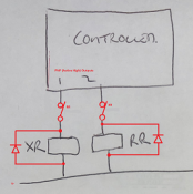
At this stage I just want to use a linear actuator to rotate a prop slightly. Next year maybe add a servo or stepper motor to make it travel.

Surely, one output could be set to OFF while the other is ON and not be floating without specific command.
 
It's your prop and display so you can do it however you would like. ACL members commenting are merely making suggestions to help it work correctly and/or properly. I tweaked the control schematic a bit to somewhat follow previous suggestions. It's attached.

I did want to comment a little about the 'only PLC interlocked without electrical or mechanical interlocks and no issues' statement. From experience I can say it doesn't work. Interlocks need designed in.

Actuator.png
 
I have designed window motor controllers for commercial applications and while I do have the microcontroller implement sanity checking and soft lockouts, I do also arrange the output switching so that a stuck relay can't cause damage. There may still be a malfunction (eg. window in wrong position), but no damage.
 
Thank you everyone for your input. My apologies if I have upset anyone. It’s impossible to know what people have done for a living or currently do and what they’re experience is when all you see is a ‘username’.

TerryK, does blue point engineering shop to Australia ? I like their 4 and 8ch relay board and their supporting document appears to explain their setup quite well. It even contains wiring diagram for communications and equipment.

Cheers
Steve
 
Back
Top