DC-DC converters and pixels.. getting your feet wet?

davrus

Silent elf
Joined
Jan 9, 2014
Messages
168
Location
Whitianga
I have some solar "fairy" LED lights. I had originally thought to cut the control unit off, and figure out what voltage to put onto the LED light wires. But then I bought some more, and discovered that while there were only two wires leaving the control unit, after the first light there were three wires, and there was a switch on the control unit to have two sets of lights alternating. Then I bought some solar meteor lights, and it got really complicated.


But now I am thinking, would it be possible to remove the rechargeable battery, and connect wires from a DC-DC converter, set down to 1.5V, to the battery connections ? (and just remember to only sequence those items at full-on, or off).


Would that work ?
 

David_AVD

Grandpa Elf
Community project designer
Generous elf
Joined
Jun 12, 2010
Messages
4,681
Location
Victoria Point (Brisbane)
I've converted sets of solar lights before. What I did however was bypass the whole power converter. How you do this can vary between light sets.

Simply supplying voltage to the battery contact may not be a good idea. This is because the controller circuit is also responsible for pushing current back into the battery during the charge (day) cycle.

Disconnecting the solar cell *should* render things safer as there's no charge source, but then you'll lose the automatic (night) operation.
 

plasmadrive

Full time elf
Joined
Jan 12, 2012
Messages
248
Location
Elk Grove, CA
David_AVD said:
I've converted sets of solar lights before. What I did however was bypass the whole power converter. How you do this can vary between light sets.

Simply supplying voltage to the battery contact may not be a good idea. This is because the controller circuit is also responsible for pushing current back into the battery during the charge (day) cycle.

Disconnecting the solar cell *should* render things safer as there's no charge source, but then you'll lose the automatic (night) operation.

Yeah, what he said!
 

multicast

Senior elf
Joined
Jul 13, 2013
Messages
715
plasmadrive said:
David_AVD said:
I'd probably only count on a efficiency of 85% max when calculating input power requirements. The efficiency will also vary of the range of current draw and well as input voltage.

Actually the ones I tested were closer to 94-96%. I was amazed. Spec is 90%. It could be that I just got a good one to test with but there was almost no loss at all.

Remember, they don't have the front end losses that AC/DC supplies have. And like any electronics, they have their sweet spot..


How did you do these measurements. A switching PSU of 95% is a very amazing thing.
 

plasmadrive

Full time elf
Joined
Jan 12, 2012
Messages
248
Location
Elk Grove, CA
Qiang Fu Kiwi said:
plasmadrive said:
David_AVD said:
I'd probably only count on a efficiency of 85% max when calculating input power requirements. The efficiency will also vary of the range of current draw and well as input voltage.

Actually the ones I tested were closer to 94-96%. I was amazed. Spec is 90%. It could be that I just got a good one to test with but there was almost no loss at all.

Remember, they don't have the front end losses that AC/DC supplies have. And like any electronics, they have their sweet spot..


How did you do these measurements. A switching PSU of 95% is a very amazing thing.
I agree. I was not expecting it to be that high.

Measurements were P in vs. P out. (E*I) standard stuff.. using a true RMS meter out... but only the power supply amp meter measuring the input. That amp meter is accurate for DC as I have checked it's calibration before. I am not sure if it is 100% accurate with a switchmode load.. but I am guessing it is close enough for round number stuff..
 

David_AVD

Grandpa Elf
Community project designer
Generous elf
Joined
Jun 12, 2010
Messages
4,681
Location
Victoria Point (Brisbane)
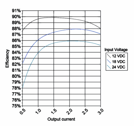
Here's a chart for a random 5V 3A DC-DC converter:
dcz5-eff.png

As you can see, the efficiency drops off markedly at low output currents. This means there's proportionally more wasted energy (heat dissipated), but luckily at those lower currents the absolute waste is fairly low.

Also (for this example converter), the efficiency is lower when the input voltage is higher. This may not be the case for all converters though. You'd really need to check the efficiency for the particular input voltage, output voltage and output current on the chosen converter.

What all of this means is that you may need to factor in these losses when calculating the power supply requirements. So if your RGB strip draws 36W on full white, the power supply could need to supply up to 45W of power to the DC-DC converter to make it happen.

Anyway, this is just some additional information to the original post to make sure people don't get caught short with power in their displays.
 

algerdes

Al Gerdes
Joined
Nov 29, 2012
Messages
288
Location
Lebanon, Illinois
Thank you for all the tech! As I sit here drawing out the new shows (yes - 2), I'm thinking of all the ways to make this stuff work to our advantage.


Same old story, great ideas - pocketbook is shrinking by the minute.
 

davrus

Silent elf
Joined
Jan 9, 2014
Messages
168
Location
Whitianga
Thanks for the info. This has been a very informative topic.


Update:
The DC-DC PCBs are small enough to be able to encase them in translucent heat shrink (after they have been wired , and the voltage set). BUT ... would they generate too much warmth, and overheat, or would the heat shrink allow enough heat to dissipate, keeping them at a reasonable operating temperature ?
 

AAH

I love blinky lights :)
Community project designer
Joined
Dec 27, 2010
Messages
4,190
Location
Eaglehawk
The ability to get rid of the heat is going to depend on how much heat is required to be got rid of. Typically I'd say if the losses in the dc-dc are more than about 3 or 4W then I'd be a little dubious about adding a further layer of thermal insulation over them. If you pop up details of the exact dc-dc and application specifics in terms of input voltage and output current then someone can probably say yay or nay with a bit better idea of what they are yaying or naying.
 

multicast

Senior elf
Joined
Jul 13, 2013
Messages
715
David_AVD said:
ortionally more wasted energy (heat dissipated), but luckily at those lower currents the absolute waste is fairly low.
Also (for this example converter), the efficiency is lower when the input voltage is higher. This may not be the case for all converters though. You'd really need to check the efficiency for the particular input voltage, output voltage and output current on the chosen converter.

Theres a whole bunch of factors in this; above graphs are typical of "Buck" type converter. Thats one thats designed to Downwards convert from one higher voltage to a lower voltage. Theres lots of different topologies. Theres a bunch of things that contribute to the efficiency and these factors all play greater or lessor amounts at various points along their operational curves. theres also a lot of different design decisions ( compromises ) you can make when you design these things..

For example, you can make a more efficient regulator by running it at lower switching frequencies, but to do that you need bigger output inductors. that means for a given current, a bigger ( and more expensive ) inductor. your faced with lots of decisions about cost, size, output ripple ( how accurately it tracks ) etc..


theres no free lunches with these things, everything is a compromise!
 

plasmadrive

Full time elf
Joined
Jan 12, 2012
Messages
248
Location
Elk Grove, CA
davrus said:
Thanks for the info. This has been a very informative topic.


Update:
The DC-DC PCBs are small enough to be able to encase them in translucent heat shrink (after they have been wired , and the voltage set). BUT ... would they generate too much warmth, and overheat, or would the heat shrink allow enough heat to dissipate, keeping them at a reasonable operating temperature ?

I don't think I would rely on heat shrink around a converter if you are using any type of power what so ever. I have some converters that are bare PCBs and are supposed to do 3amp max. without a heatsink, 1.5amps I all I could push them to without them getting over 100C. The converters I linked to that are potted and have a heat sink, got about 5-9 F above ambient with a 4 amp load over 24hrs of testing. Load was constant, ambient was between 70-76 F during the entire test.
 

plasmadrive

Full time elf
Joined
Jan 12, 2012
Messages
248
Location
Elk Grove, CA
David_AVD said:
Here's a chart for a random 5V 3A DC-DC converter:
dcz5-eff.png

As you can see, the efficiency drops off markedly at low output currents. This means there's proportionally more wasted energy (heat dissipated), but luckily at those lower currents the absolute waste is fairly low.

Also (for this example converter), the efficiency is lower when the input voltage is higher. This may not be the case for all converters though. You'd really need to check the efficiency for the particular input voltage, output voltage and output current on the chosen converter.

What all of this means is that you may need to factor in these losses when calculating the power supply requirements. So if your RGB strip draws 36W on full white, the power supply could need to supply up to 45W of power to the DC-DC converter to make it happen.

Anyway, this is just some additional information to the original post to make sure people don't get caught short with power in their displays.

Not all are created equal. That indeed may be a typical chart.. and perhaps in my write up I should have put something about testing what you are using prior to final numbers.. or maybe even bumped up the head room factor..

In the next week or so as time permits I will grab one of the converters I used and retest it. This time I will use a true RMS meter on both the in and out.. Lets see where it takes us. Maybe I just got a sweet one for my original testing or maybe my power supply meter was inaccurate with the non linear load. I will report back with I have time.
 

davrus

Silent elf
Joined
Jan 9, 2014
Messages
168
Location
Whitianga
David, can you please expand upon your reasoning for replacing the trim pot on the second example (LM2596).
You don't show a photo of the replacement trim pot.


Every man and a dog seems to make variations on the LM2596 model. Try a search on Aliexpress.


You say it is an older product. What newer one do you recomend ?


I've also tried this product. It has a few bells and whistles, which adds to the price, but otherwise it is a basic LM2596 unit. (In case you are wondering - the USB connection is so you can charge USB devices - is that a bell or a whistle?)
 
Top